EasyManua.ls Logo

Crown MARCO-TECH 5000VZ User Manual

Crown MARCO-TECH 5000VZ
30 pages
To Next Page IconTo Next Page
Page #1 background imageLoading...
Page #1 background image
Notes
MACRO-TECH 5000VZ
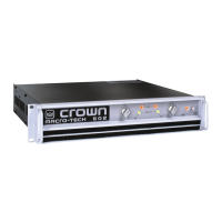
OVERVIEW
At
first glance
the
MA-5000VZ
looks
a
great deal
Hke any
other
MA
Series
amplifier, except that
¡t is
physically larger
and
puts
out
more
power.
The
internal
structure
of the
MA-5000VZ
is,
however, quite
different
from
other models
in the MA
une.
To the
user, this
one is
like
the
others,
but
with
a
f
ew
more
f
eatures.
To the
technician,
this
amplifier
representsaradicaldeparturefromthe"normal"Crowndesign.
Previous
chapters covered
the
"normal," this chapter
shall
endeavorto
take
the
MA-5000VZ
as a
unique
entrty.
The
amplifier
¡s
protected
from
all
common hazards that plague high-
power
amplifiers, including
shorted,
open
or
mismatched
loads,
overloaded power
supplies,
excessive temperature,
chain-destruction
phenomena,
input-overload
damage,
and
high-frequency blowups.
The
unit
protects
loudspeakers
from
DC in the
input
signal
and
from
turn-on
and
turn-off
transients.
It
also
detects
and
prevenís
unwanted
DC
on the
outputs. Additional protection features include input current
sense,
overvoltage
(AC
mains).
A
mode
of
protection which
may
be
switched
on or
off
is
called
Loudspeaker Offset Integration (LOI).
The
LOI
circuit, when switched
on,
prevenís
excessive bass frequency
cone
excursions
below
the
audible frequency range.
It
operates essentially
as a
band-pass filter.
The
low
frequencies
are
rolled
off at
18dB/oclave
with
a
-3dB
córner
of
35
Hz
(Butterworth
response).
Ullra-sonics
are
rolled
off
wilh
a
second
order
Bessel
response
and
-3dB córner
of
SOkHz.
A
compression
circuil
in
each channel
may be
switched
off,
on
slow,
or
on
fast
by
swilches
on
Ihe
rear panel. This compressor
is
aclivaled
by
eilherinputoverloadord¡stort¡on(cl¡pping).
Compression ratio
is
infinite
(operates
as a
peak
limiter).
Thefour-quadrant
lopology
used
in the
grounded
oulpul
slages
is
called
Ihe
grounded bridge
and
makes
full
use of
Ihe
power supplies. This
patentad
lopology
also
makes
peak-lo-peak
voltages
available
lo
the
load which
are
twice
the
vollage
any
output
device
¡s
ever exposed
to.
The
grounded bridge
is
covered
in
detail
in the
BASICS
seclion
of
this
texl.
MA-5000VZ
- 1
Question and Answer IconNeed help?

Do you have a question about the Crown MARCO-TECH 5000VZ and is the answer not in the manual?

Crown MARCO-TECH 5000VZ Specifications

General IconGeneral
BrandCrown
ModelMARCO-TECH 5000VZ
CategoryAmplifier
LanguageEnglish

Summary

Overview

Output Stage Circuitry

VZ Power Supply Technology

VZ Supply Introduction

Introduces VZ supply concept, similar to MA-3600VZ.

Variable Impedance (VZ) Explained

Defines VZ as Crown's patented articulated power supply technology.

VZ Articulated Supply Solution

Explains how VZ reduces voltage to match requirements, reducing heat.

VZ Supply Operation Modes

VZ Supply Segmentation

VZ supply divided into segments to match transistor voltage/current needs.

VZ Supply Modes (Parallel/Series)

VZ divides into two parts: parallel (low voltage, high current) and series (high voltage, low current).

VZ Normal Operating Mode

Power transistors stay cooler in parallel mode, reducing needless heat dissipation.

VZ High Voltage Mode (Series)

VZ switches to series mode for high voltage needs, ensuring full voltage when required.

VZ Switching Trigger

Sensing circuitry monitors signal voltage to determine when to switch VZ modes.

VZ Supply Control and Switching

VZ Switching Circuitry Benefits

Switching circuitry prevents distortion, yields dynamic transfer, and ensures best power matching.

VZ Control Circuit Logic

VZ control senses audio level to switch between parallel (high current) and series (high voltage) modes.

MOSFET Operation in VZ Supply

Explains how MOSFETs turn on to force supplies into series mode for higher voltage.

VZ Supply and ODEP Interaction

ODEP Interaction with VZ Modes

ODEP activation locks VZ into low voltage mode to cool amplifier faster.

VZ Supply Circuitry Details

555 Timer Control of VZ Switching

555 timer output determines MOSFET switching, enabling articulation.

ODEP Protection Theory

ODEP Purpose and Function

ODEP protects output stages from thermal conditions using an analog signal.

ODEP Control of Stages

ODEP signal controls Voltage Translator and Low Side bias, removing excess drive.

Thermal Sensors and ODEP Integration

Thermal sensors provide operating temperature info to ODEP for protection scheme.

ODEP Amplifier and Output Signals

ODEP Circuit Components

ODEP Limiting Trigger Condition

Exceeding 130°C causes U117A output to trigger hard ODEP limiting.

ODEP Output Signal Routing

ODEP Control Signal Integration

ODEP Output Control Logic

Front End Signal Path Theory

Amplifier Protection Systems

MA-5000VZ Protection Mechanisms

Lists protection mechanisms like ODEP, current limit, over-voltage, thermal, etc.

Specific Protection Mechanisms

Details ODEP, current limit, over-voltage, DC/LFI, thermal, power loss, LOI, slew rate limit.

Soft-Start Operation Details

Over-Voltage Protection

Over-Voltage Protection Purpose

Shuts down amplifier during AC mains over-voltage conditions.

Over-Voltage Sensing Method

Sensed by pulsed DC signal from low voltage supply's full-wave rectifier.

U707D Over-Voltage Response

U707D shifts low if pulsed DC indicates high voltage, triggering LED and OV1 signal.

OV1 Signal to U211C

Low OV1 signal causes U211C to shift low, initiating shutdown.

C120 Discharge During Over-Voltage

Low output from U211C discharges C120 via D1, initiating shutdown.

Over-Voltage Shutdown Sequence

C120 discharge causes relay dropout, soft-start reset, and audio clamping.

Over-Voltage Fault Type

Over-voltage is a non-latching fault condition.

DC/LFI Protection

DC/LFI Protection Purpose

Interrupts amplifier channel for DC or very low frequency output.

DC/LFI Sensing Method

Senses voltage and current via feedback loop for DC/LFI detection.

RC Network for LFI Prevention

RC network at U109C/D input prevents LFI activation with normal audio frequencies.

Protection Signal Integration

OV Signal Generation

Over-Voltage and Thermal Switch info combine to produce "OV" signal for U211C.

DC/LF Shutdown Trigger

DC/LF detection outputs low, discharging C120 via D102 to shut down supply.

DC/LF LED Indication

Low signal also lights the DC/LF red LED on the main module.

Specific Protection Circuitry

DC/LF Circuitry Details

Details the circuitry responsible for detecting DC or low frequency output.

Common Mode Output Current Fault Circuit

Shuts down amplifier on high current in both positive and negative output stages.

Common Mode Fault Condition

High current in both output halves simultaneously causes shutdown.

Latching Protection Function

This is the only latching protection function in the MA-5000VZ.

Comprehensive Protection Mechanisms

U115 Specialty Device Function

U115 acts as both an Opto-SCR and conventional SCR, requiring simultaneous firing.

U115 Latching Mechanism

High currents in both sides cause U115 SCR to latch on until unit is turned off.

Common Mode Latch Indication

Latching causes red LED to light and a low FAULT signal, which discharges C120.

Output Thermal Protection Reference

Output over-temperature protection discussed in ODEP Circuitry section.

ODEP Thermal Sensing

Calibrated temperature sense drives U117A, leading to hard ODEP if temp exceeds limit.

ODEP Hard Limit Trigger

Heatsink temp over 130°C triggers hard ODEP, clamping audio.

ODEP Clamping Effect

Hard ODEP does not shut down but clamps the audio signal.

Power Loss (Brown-Out) Sensing

Senses "brown-out" conditions on AC service via low-voltage supply monitoring.

Power Loss Sensing Point

Sensing is accomplished by monitoring the low-voltage power supply at U111A.

Power Loss Capacitor Buffering

Local capacitors keep U111A powered briefly after low voltage supply drops.

RC Network Action on Power Loss

RC network causes U111A output to shift low instantly upon low voltage loss.

C120 Discharge and Shutdown Initiation

Negative potential discharges C120, opening relay and resetting soft-start.

C120 Discharge Timing Importance

Essential to discharge C120 immediately upon power restoration to prevent issues.

Power Loss Audio Muting

Output mutes audio via ±LL and ±LH to prevent turn-off noise.
Fan Control System

Mono Mode Operation

Related product manuals