Do you have a question about the Crown Micro-Tech 2401 and is the answer not in the manual?
Describes Crown's warranty terms and conditions applicable globally.
Details Crown's warranty terms and conditions specific to North America.
Crucial guidelines on output wiring, electric shock prevention, and operational safety.
Instructions for unpacking and checking the amplifier for transit damage.
Highlights technological advancements, benefits, and proprietary features.
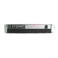
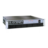
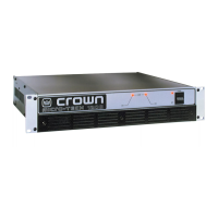
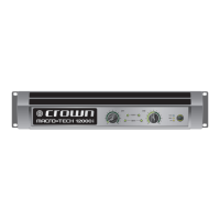
Details on filter grille, indicators, power switch, and stereo/mono selection.
Describes level controls, input/output jacks, ground lift, and cover plate access.
Proper installation methods and air flow requirements for optimal performance.
How to wire the amplifier for standard two-channel stereo operation.
Connects the load for bridge-mono mode, requiring specific wiring configurations.
Details wiring procedures for parallel-mono mode, emphasizing jumper use.
Recommended wiring for various input signal sources and connector types.
Addressing subsonic, RF, and ground loop issues with appropriate filtering.
Proper loudspeaker connection and selecting the correct wire gauge for cables.
Preventing oscillations and protecting inductive loads with specific circuits.
Using fuses to protect loudspeakers from thermal damage and transient voltages.
Details on power cords, voltage, and frequency requirements by region.
Safe operating practices, indicator functions, and essential precautions.
Details on ODEP, thermal, drive, and fuse/breaker protection mechanisms.
Overview of sensitivity, ground lift, and stereo/mono mode switches.
Cleaning instructions for the air intake dust filter to ensure proper cooling.
High-level description of design, heat sink technology, and thermal management.
Explanation of signal path, protection mechanisms, and operation in various modes.
Frequency response, distortion, signal-to-noise ratio, damping factor, and crosstalk.
Guaranteed minimum power output levels for MT-600 in various modes and loads.
Guaranteed minimum power output levels for MT-1200 and MT-2400.
Explanation of burst and single-cycle power measurements and their implications.
Power levels for MT-600 under burst and single-cycle test conditions.
Power levels for MT-1200 and MT-2400 under burst and single-cycle test conditions.
Equations and assumptions used for calculating power draw and thermal dissipation.
Detailed tables for MT-600 power consumption and heat output at various duty cycles.
Detailed tables for MT-1200 and MT-2400 power consumption and heat output.
Details on alternative fan blades for specific cooling requirements.
Description of MT-XLR and MT-BB accessory panels for input connectivity.
Procedures for global warranty claims and repair service.
Guidelines for using authorized service centers or factory repair in North America.
| Channels | 2 |
|---|---|
| Input Impedance | 20 kOhms balanced, 10 kOhms unbalanced |
| Frequency Response | 20Hz - 20kHz |
| Total Harmonic Distortion | <0.05% |
| Input Sensitivity | 1.4V |
| Signal-to-Noise Ratio | > 100 dB |
| Cooling | Forced Air |
| Dimensions | 19" x 3.5" x 16.25" |





 Loading...