Page 8
Micro-Tech 600/1200/2400 Power Amplifiers
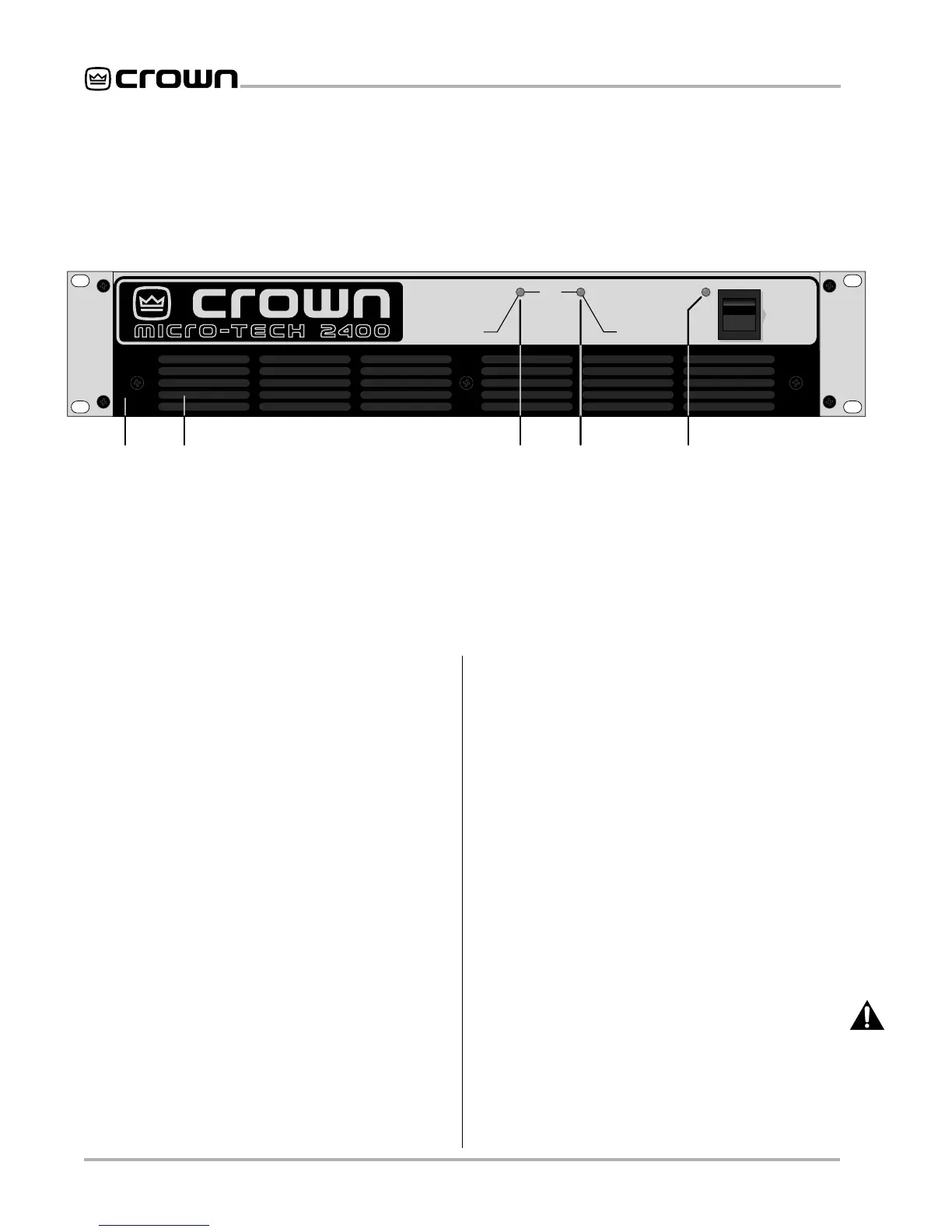
Fig. 2.1 Front Facilities
ODEP
CH1 CH2
POWER
OFF
AB CC D
2 Facilities
A. Filter Grille
This metal grille supports and protects the dust
filter (B). To clean the dust filter, detach the grille by
removing the three screws that hold it in place.
B. Dust Filter
The dust filter removes large particles from the air
drawn by the cooling fan. Check the filter regularly to
prevent clogging (see Sections 3.2 and 4.5).
C.
ODEP
Indicators
During normal operation of the Output Device Emula-
tion Protection circuitry, these amber indicators glow
brightly to show that reserve thermodynamic energy is
present. They dim proportionally as energy reserves
decrease. In the rare event that energy reserves are
depleted, the
ODEP
indicators turn off and the protec-
tion circuitry proportionally limits output drive so the
amplifier can safely continue operating even under
severe conditions. These indicators also help identify
more unusual operating conditions (see Section 4.2).
D. Enable Indicator
This indicator lights when the amplifier is turned on, AC
power is available and the low-voltage power supply
and fan are operational (see Section 4.2).
E. Power Switch
This rocker switch is used to turn the amplifier on and
off. When turned on, the output is muted for approxi-
mately four seconds to protect your system from start-
up transients. (To change the start-up delay time,
contact Crown’s Technical Support Group.)
F. Power Cord
All units are shipped with an appropriate plug and cord
for the required AC voltage (see Figure 3.16). Also, re-
fer to Section 7 for power usage information.
G. Stereo/Mono Switch
The amplifier’s three operating modes are controlled
by this switch. Use Stereo mode for normal two-chan-
nel operation, Bridge-Mono mode to drive a single
channel with a load impedance of at least 4 ohms, and
Parallel-Mono mode to drive a single channel with a
load impedance less than 4 ohms. Important: Turn off
the amplifier before changing the stereo/mono
switch (see Section 3.3).
H. Reset Switches (
Micro-Tech 2400
only)
The
Micro-Tech 2400
has two push-button reset
switches on the back panel that are used to reset the
circuit breakers for the high-voltage power supplies.