Page 11
Micro-Tech 600/1200/2400 Power Amplifiers
the rack so it blows outside air into the space between
the door and the front of the amplifiers. This will pres-
surize the “chimney” behind the door (Figure 3.3, Op-
tion 1). The blower should not blow air into or take air
out of the space behind the amplifiers. For racks with-
out a front door, you can evacuate the rack by mount-
ing the blower at the top of the rack so air blows out the
back (Figure 3.3, Option 2). You can estimate a rack’s
required air flow by adding each unit’s maximum air
flow rating. Each
Micro-Tech 600
and
1200
can move
35 cubic feet (1 cubic meter) of air per minute, and
each
Micro-Tech 2400
can move 45 cubic feet (1.3
cubic meters) of air per minute. So if you put one of
each in a rack, you would need 115 cubic feet (3.2 cu-
bic meters) of air flow through the rack per minute un-
der worst-case conditions (35 cubic feet + 35 cubic
feet + 45 cubic feet = 115 cubic feet).
Another cooling problem to consider is high ambient
air temperature. If the ambient air temperature is ex-
tremely high,
ODEP
may reduce the output to protect
the amplifier even when it is receiving the maximum
recommended air flow. Under these unusual condi-
tions, it may be necessary to use air conditioning for
supplemental cooling. Air conditioning is rarely a ne-
cessity because internal fans and rack-mounted blow-
ers almost always provide enough air flow for the most
extreme conditions. Still, air conditioning helps reduce
the ambient temperature of the air flowing through the
rack. If you plan to use air conditioning, refer to Sec-
tion 7 for information on calculating the hourly thermal
dissipation of your system.
3.3 Wiring
The following section describes common ways to in-
stall your amplifier in a sound system. The input and
output terminals are located on the back panel. Please
use care when making connections, selecting signal
sources and controlling the output level. The load you
save may be your own! Crown assumes no liability for
damaged loads resulting from careless amplifier use
or deliberate overpowering.
CAUTION: When making or changing connections,
always disconnect the AC power and turn the level
controls off (fully counterclockwise). This is very im-
portant because it reduces the chance of loud blasts
that can cause loudspeaker damage.
Micro-Tech
amplifiers may be operated in one of three
modes (Stereo, Bridge-Mono and Parallel-Mono) by
switching the stereo/mono switch on the back panel.
There are VERY IMPORTANT wiring differences among
these three modes which are discussed next.
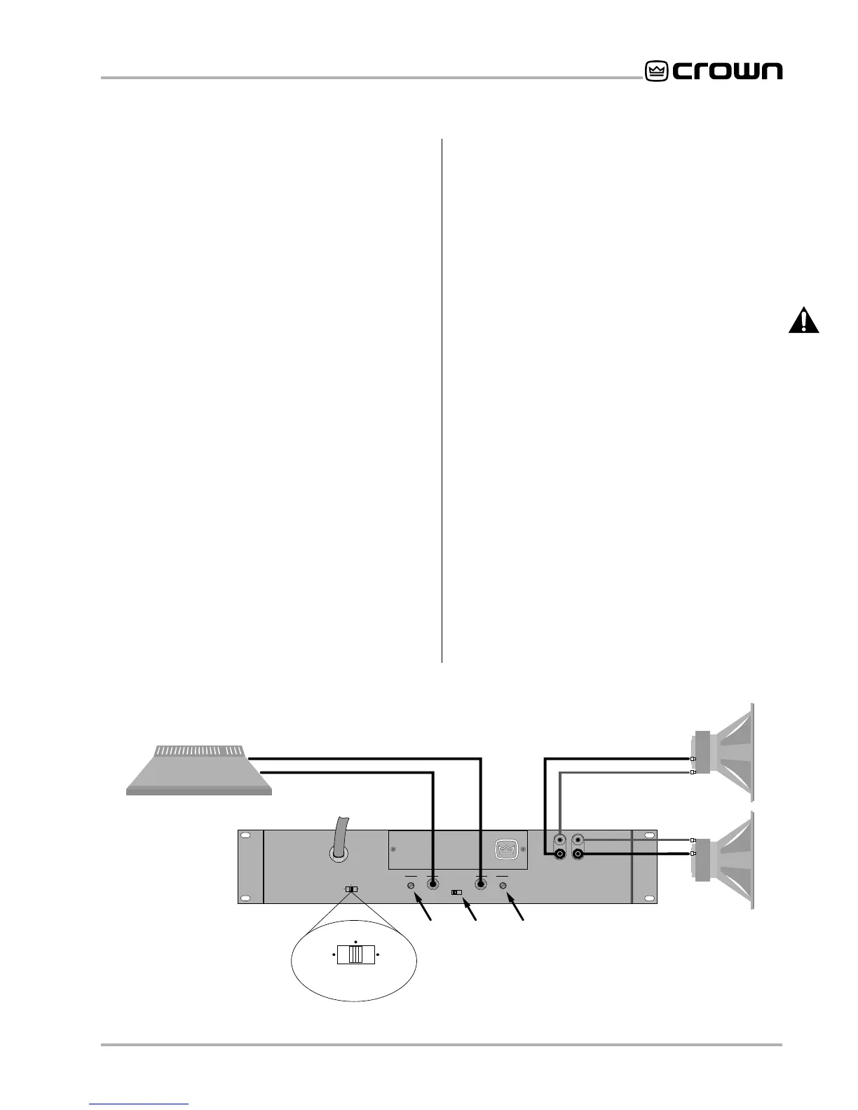
3.3.1 Stereo (Two-Channel) Operation
In Stereo mode, installation is very intuitive: input chan-
nel 1 feeds output channel 1, and input channel 2 feeds
output channel 2. To put the amplifier into Stereo mode,
first turn it off, then slide the stereo/mono switch to the
center position, and properly connect the output wir-
ing as shown in Figure 3.4. Each channel has a pair of
binding posts for easy loudspeaker cable connection.
Observe correct polarity, and be very careful not to
short the two channels together.
Fig. 3.4 Stereo Wiring
STEREO MODE
MIXER
LOUDSPEAKERS
MICRO-TECH AMPLIFIER
+
–
+
–
CHANNEL 1
CHANNEL 2
CHANNEL 1
CHANNEL 2
STEREO
BRIDGE
MONO
PARALLEL
MONO
CAUTION:
TURN OFF AMPLIFIER
BEFORE CHANGING THIS SWITCH.
STEREO
BRIDGE
MONO
PARALLEL
MONO
CH-2
CH-1
CH.2
LEVEL
CONTROL
GROUND
LIFT
SWITCH
CH.1
LEVEL
CONTROL