Page 21
Micro-Tech 600/1200/2400 Power Amplifiers
4.4 Controls
The power switch is located on the front panel so you
can easily turn the amplifier on or off. If you ever need
to make any wiring or installation changes, don’t forget
to disconnect the power cord. Please follow these
steps when first turning on your amplifier:
1. Turn down the level of your audio source. For
example, set your mixer’s volume to “∞” (off).
2. Turn down the amplifier’s level controls located
on the back panel.
3. Turn on the power switch. The enable indicator
beside the switch should glow.
4. After the turn-on delay, turn up the level of your
audio source to the maximum desired level.
5. Turn up the level controls on the back panel of
the amplifier until the maximum desired loud-
ness or power level is achieved.
6. Turn down the level of your audio source to its
normal range.
You can adjust each channel’s output using the back
panel level controls. These controls are located on
the back panel to help prevent unwanted tampering.
A three-position input sensitivity switch is located in-
side the amplifier’s back panel cover plate. The switch
is set at the factory to a sensitivity of 0.775 volts for
standard 1 kHz power into 8 ohms. If desired, the sen-
sitivity can be switched to 1.4 volts for standard 1 kHz
power into 8 ohms, or a voltage gain of 26 dB. The 26
dB gain setting is equivalent to a sensitivity of 2.1 volts
for the
Micro-Tech 600
, 2.5 volts for the
Micro-Tech
1200
and 3.2 volts for the
Micro-Tech 2400
.
To change the input sensitivity:
1. Turn off the amplifier and disconnect its power
cord from the AC power source.
2. Remove the back panel cover plate (or input
connector accessory).
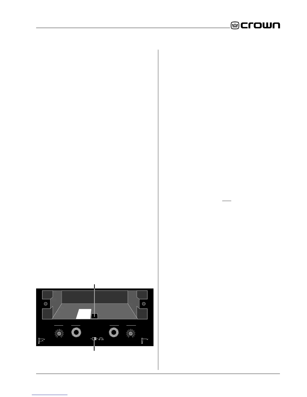
3. Locate the access hole for the sensitivity switch
inside the chassis opening (Figure 4.2). The
sensitivity switch will not be visible because it is
mounted below the hole. Use your little finger to
reach it.
4. Set the switch to the desired position noted on
the label beside the access hole.
5. Replace the back panel cover plate (or input
connector accessory) and restore power.
The back panel stereo/mono switch is used to select
Stereo, Bridge-Mono or Parallel-Mono operating mode.
Power must be removed from the amplifier before se-
lecting a different operating mode. There are also im-
portant wiring differences among the different modes,
so be sure to read Section 3.3 before changing the
position of the stereo/mono switch.
The ground lift switch is located on the back panel
and can isolate the input signal grounds from the AC
(chassis) ground. It affects only the phone jack inputs
and has no affect on accessory input connectors. Slid-
ing the switch to the left isolates or “lifts” the grounds
by placing an impedance between the sleeve of each
phone jack and the AC ground.
The
Micro-Tech 2400
has two reset switches for its
high-voltage power supplies. Refer to Section 4.3.5 in
the unusual event of a tripped breaker.
4.5 Filter Cleaning
A dust filter is provided on the air intake to the cooling
system (Figure 2.1). If this filter becomes clogged, the
unit will not cool as efficiently as it should and may pro-
duce lower-than-normal output levels due to high heat
sink temperature.
To remove the filter, use a phillips screwdriver to re-
move the three screws that hold the front grille in place.
Wash the filter with mild dishwashing detergent and
warm water. Be sure to dry the filter before reinstalling
it. Replacement filters may be ordered from the fac-
tory.
Dust filters are not 100% efficient—depending on the
local environment, the internal heat sinks of the ampli-
fier will benefit from periodic cleaning by a qualified
technician. Internal cleaning information is available
from our Technical Support Group.
Fig. 4.2 Input Sensitivity and Ground Lift Switches
0.77 V
26 dB
SENSITIVITY SWITCH INSIDE ACCESS HOLE
1.4 V
UNBALANCED
INPUT WIRING
BALANCED
INPUT WIRING
+
–
TIP
RING
SLEEVE
GND
+
TIP
SLEEVE
GND
THIS AMPLIFIER IS EQUIPPED WITH SELECTABLE INPUT SENSITIVITY. REMOVE COVER PLATE (ABOVE) TO ACCESS SENSITIVITY SWITCH.
CH-2
INPUT GROUND LIFT
(AFFECTS PHONE INPUTS ONLY.)
(MONO)
INPUT
GAIN
CH-1
INPUT
GAIN
LIFT
0
1
2
3
4
5
6
7
8
9
10
11
12
0
1
2
3
4
5
6
7
8
9
10
11
12
GROUND LIFT SWITCH