Page 9
Micro-Tech 600/1200/2400 Power Amplifiers
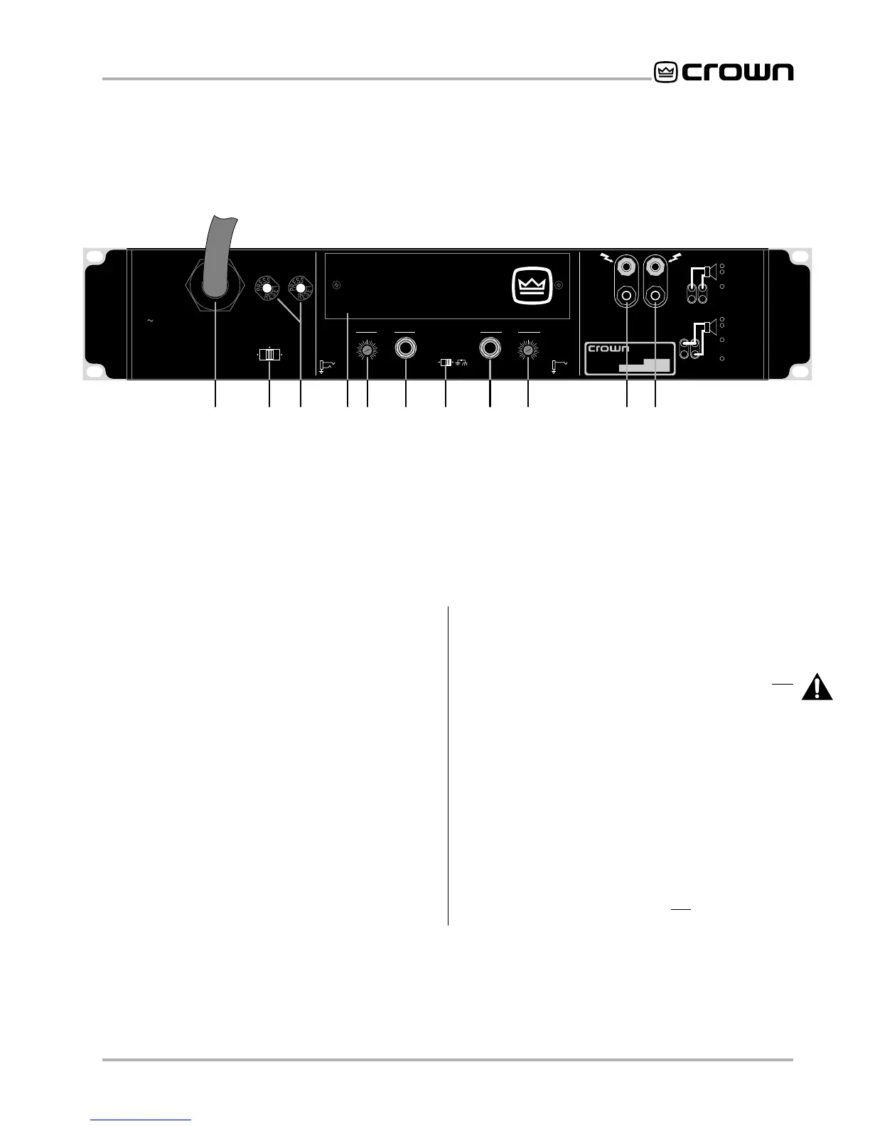
Fig. 2.2 Rear Facilities
CAUTION:
THIS COVER IS NECESSARY FOR
EFFICIENT COOLING OF THE AMPLIFIER.
REMOVE ONLY TO ACCESS GAIN SWITCH.
0
1
2
3
4
5
6
7
8
9
10
11
12
0
1
2
3
4
5
6
7
8
9
10
11
12
BRIDGE-MONO WIRING
TURN AMPLIFIER OFF.
SET STEREO/MONO
SWITCH TO
BRIDGE-MONO.
OUTPUT ACROSS
RED TERMINALS
ONLY. (CH-1
IS POSITIVE.)
PARALLEL-MONO WIRING
TURN AMPLIFIER OFF.
SET STEREO/MONO
SWITCH TO
PARALLEL-MONO.
ADD JUMPER (14
GAGE OR LARGER)
ACROSS RED
TERMINALS.
OUTPUT ACROSS CH-1
TERMINALS ONLY.
1
2
3
4
1
2
3
CH-2 CH-1
+
–
–
+
INPUT GROUND LIFT
(AFFECTS PHONE INPUTS ONLY.)
CAUTION:
TURN OFF AMPLIFIER
BEFORE CHANGING THIS SWITCH!
STEREO
BRIDGE
MONO
PARALLEL
MONO
CLASS 1
OUTPUT
WIRING
REQUIRED.
WARNING:
TO REDUCE THE RISK OF FIRE OR
ELECTRIC SHOCK DO NOT EXPOSE THIS EQUIPMENT
TO RAIN OR MOISTURE.
OUTPUTS
LIFT
REG. U.S. PAT. OFF.
4,330,809
4,611,180
MODEL: MICRO-TECH 2400 SERIES
AC VOLTS: 120 AMPS: 17 60 Hz
MAXIMUM OUTPUT: 900 WATTS
PER CHANNEL INTO 2 OHMS AT 1 KHz
WITH NO MORE THAN 0.1% THD.
UNBALANCED
INPUT WIRING
BALANCED
INPUT WIRING
+
–
TIP
RING
SLEEVE
GND
+
TIP
SLEEVE
GND
CH-2
(MONO)
INPUT
GAIN
CH-1
INPUT
GAIN
THIS AMPLIFIER IS EQUIPPED WITH SELECTABLE INPUT SENSITIVITY. REMOVE COVER PLATE (ABOVE) TO ACCESS SENSITIVITY SWITCH.
®
INTERNATIONAL, INC.
ELECTRONIC EQUIPMENT
ELKHART, IN 46517
MADE IN U.S.A.
SERIAL NUMBER
0000
000000
FGHI K KL MMJJ
PUSH TO RESET
I. Cover Plate
This cover plate is removed when changing the
amplifier’s input sensitivity (see Section 4.4) or install-
ing an
MT-XLR
or
MT-BB
accessory (see Section 8.2).
❑ Input Sensitivity Switch
The three-position input sensitivity switch is located in-
side the amplifier behind the cover plate (I). Settings
include 0.775 volts and 1.4 volts for standard 1 kHz
power, and 26 dB gain (see Section 4.4).
J. Level Controls
These back panel level controls are used to set the
amplifier’s output levels (see Section 4.4). Be sure to
turn down the channel 2 level control (fully counter-
clockwise) when operating in Bridge-Mono mode.
K. Balanced Phone Jack Inputs
A balanced ¼-inch phone jack input is provided for
each channel. They may be wired for balanced (tip,
ring and sleeve) or unbalanced (tip and sleeve) opera-
tion (refer to Section 3.3.4). XLR and barrier block in-
put connectors are available with the
MT-XLR
and
MT-BB
accessories (see Section 8.2). Caution: Do not
use the channel 2 input in either mono mode.
L. Ground Lift Switch
This switch is used to isolate the phone jack signal
grounds from the AC power (chassis) ground. Moving
the switch to the “lift” position helps prevent the hum
associated with ground loops (see Section 4.4).
M. Output Jacks
A pair of versatile binding posts is provided for output
connection to each channel. Loudspeakers can be
easily connected using banana plugs, spade lugs or
bare wire (European models do not accept banana
plugs). See Section 3.3.