EasyManua.ls Logo

Crown Com-Tech CT-400 User Manual

Crown Com-Tech CT-400
39 pages
To Next Page IconTo Next Page
Page #1 background imageLoading...
Page #1 background image
Com-Tech 400 Amplifier Service Manual
1
COM-TECH
®
400
POWER AMPLIFIER
SERVICE MANUAL
K-SVCCT400
12-95
Com-Tech
®
, ODEP
®
and Crown
®
are registered trademarks of Crown International, Inc.
Mailing Address:
P.O. Box 1000
Elkhart, IN U.S.A. 46515-1000
Shipping Address:
57620 C.R. 105
Elkhart, IN U.S.A. 46517
©1995 by CROWN INTERNATIONAL, INC.
Model CT400B

Other manuals for Crown Com-Tech CT-400

Question and Answer IconNeed help?

Do you have a question about the Crown Com-Tech CT-400 and is the answer not in the manual?

Crown Com-Tech CT-400 Specifications

General IconGeneral
BrandCrown
ModelCom-Tech CT-400
CategoryAmplifier
LanguageEnglish

Summary

Safety and Handling Information

Safety Warnings and Cautions

Essential safety warnings and cautions for amplifier operation and servicing.

Introduction to the Service Manual

Manual Scope and Warranty

Details the manual's coverage, intended audience, and warranty service information.

Parts Information and Ordering

Part Identification and Procurement

Covers part numbering systems, standard/special parts, ordering, shipment, and terms.

Technical Specifications

Performance and Electrical Characteristics

Details power output, frequency response, SNR, THD, and electrical performance parameters.

Mechanical, Input/Output, and Protection Specs

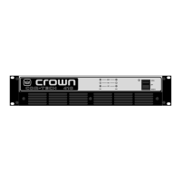
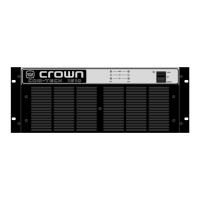
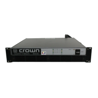
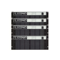
Covers physical dimensions, connectors, controls, indicators, and protection systems.

Theory of Operation

Amplifier Design Principles

Covers overview, features, front end stages, and voltage amplification.

Output Stage and Protection Circuits

Explains the grounded bridge topology, high/low side stages, and ODEP protection.

Electrical Checkout Procedures

Test Setup and Initial Adjustments

Covers general conditions, DC offset, bias, and ODEP voltage adjustments.

Performance Verification Tests

Procedures for power draw, gain, phase response, current limit, and crosstalk.

Load, Limiting, and Noise Measurements

Tests for output power, reactive loads, ODEP limiting, LF protection, and SNR.

Distortion, Clipping, and Post-Test Procedures

Covers IM distortion, clipping tests, and returning controls to factory settings.

Non-Module Parts Lists

General, Power Supply, and Output Assembly Parts

Lists supplemental items, power supply components, and output assembly parts.

Panel and Chassis Assembly Parts

Lists parts for back panel, front chassis, and main chassis assemblies.

Sub-Assembly and Miscellaneous Parts

Lists parts for PIP-BB, fan assemblies, and other miscellaneous items.

Module and Schematic Information

Module History and Types Overview

Details module revisions and categorizes module types (Output, Main, Control, Display).

Schematic Identification Guidance

Provides guidance for selecting the correct schematic based on board revisions.

Control Module Parts Lists

Q42762-7, Q43214-8, and Q43242-9 Control Modules

Lists components for specified control modules.

Display Module Parts List

Q42706-4 Display Module Components

Lists capacitors, diodes, ICs, LEDs, transistors, and resistors for the display module.

Output Module Parts Lists

Q42716-3 and Q42888-0 Output Module Components

Lists parts for the Q42716-3 and Q42888-0 output modules.

Q42969-8 and Q43188-4 Output Module Components

Lists parts for the Q42969-8 and Q43188-4 output modules.

Main Module Parts Lists

Q43012-6 and Q43043-1 Main Module Components

Lists parts for the Q43012-6 and Q43043-1 main modules.

Q43129-8 Main Module Components

Lists parts for the Q43129-8 main module.

Q43238-7 Main Module Components

Lists parts for the Q43238-7 main module.

Related product manuals