Do you have a question about the Crown DC-300A and is the answer not in the manual?
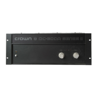
Describes the DC-300A amplifier's dual-channel, high-power, direct-coupled design and features.
Details installation and operation instructions for the DC-300A amplifier.
Instructions for inspecting the unit for damage upon receipt and saving packing materials.
Guidance on rack mounting and ensuring adequate ventilation for the unit.
Details amplifier protection against common hazards like shorts, overload, and temperature.
Discusses common load protection schemes like fuses and other methods.
Lists essential precautions for proper and safe amplifier usage.
Guidance on connecting output lines, including precautions for connectors.
Covers connecting input lines, avoiding signal issues, ground loops, and feedback.
Information on connecting power, including voltage settings and adapters.
Details the front panel controls: level controls, power switch, and pilot light.
Steps for a standard Hi-Fi setup, including connections and gain control adjustment.
Instructions for cleaning the front panel and back chassis without damage.
Overview of the circuitry to aid service technicians in understanding operation.
Explains the direct-coupled design, performance features, and technology used.
Describes the AB+B output circuit, driver transistors, and power operation.
Details the voltage-induced turn-on of limiting transistors for overload protection.
Explains the voltage doubler, current sources, and bias servo circuits.
Covers input signal path, level controls, IC op-amps, and offset voltage adjustment.
Provides technical info for servicing and repairing the DC-300A amplifier.
Outlines rules for user servicing and returning units for factory service.
Details CROWN's warranty guarantees for performance and component defects.
Steps for partially disassembling the amplifier for bench testing and servicing.
Procedure for removing the front panel and chassis cover for access.
Steps to remove the chassis cover assembly from the main chassis.
Instructions for replacing components on the main PC board.
Procedure for replacing the input level potentiometers.
Steps for replacing the main power switch.
Procedure for replacing the thermal switches on the heatsinks.
Instructions for replacing the bridge rectifier component.
Procedure for replacing the main filter capacitors.
Steps for replacing the output coils.
Detailed procedure for replacing output and driver transistors.
Lists recommended test equipment for servicing the amplifier.
Emphasizes the importance of calibrated test equipment for accurate results.
Lists essential precautions for obtaining accurate test measurements.
Provides a general procedure for diagnosing and identifying amplifier problems.
Steps for applying power to the amplifier and checking for initial issues.
Procedure to check and adjust input/output offset voltages.
Procedure to check and adjust the bias level voltage.
Test procedure to check amplifier output with a 1KHz input signal.
Test procedure to check amplifier output with a 1KHz input and load.
Tests to verify operation of clipping and protection memory circuits.
Test to check amplifier output waveform at 20KHz.
Test to examine frequency response and rise time with square wave input.
Procedure to measure IM distortion levels at various output powers.
Test to measure amplifier's hum and noise levels.
Procedure to check the amplifier's power consumption when idling.
Detailed procedure for checking and adjusting bias level voltage.
Procedure for adjusting input/output offset voltage controls.
Details a parts kit available from CROWN for repair jobs.
Explains how to use schematics and parts lists for servicing.
Discusses using standard vs. factory replacement parts.
Information on application notes for component changes and special applications.