EasyManua.ls Logo

Crown DCi 4|300N User Manual

Crown DCi 4|300N
66 pages
To Next Page IconTo Next Page
Page #1 background imageLoading...
Page #1 background image
Obtaining Other Language Versions: To obtain information in another language about the use of this product, please contact your local Crown Distributor. If you need
assistance locating your local distributor, please contact Crown at 574-294-8000.
This manual does not include all of the details of design, production, or variations of the equipment. Nor does it cover every possible situation which may arise during
installation, operation or maintenance.
The information provided in this manual was deemed accurate as of the publication date. However, updates to this information may have occurred. To obtain the latest
version of this manual, please visit the Crown website at www.crownaudio.com.
Trademark Notice: Com-Tech, BCA, Crown, Crown Audio, Amcron and Multi-Mode are registered trademarks of Crown International. DriveCore, DriveCore Install,
IQwic, PIP and PIP2 are trademarks of Crown International. Other trademarks are the property of their respective owners.
Some models may be exported under the name Amcron
®
© 2013 by Harman International
®
, Inc. 1718 W. Mishawaka Rd., Elkhart, Indiana 46517-9439 U.S.A. Telephone: 574-294-8000
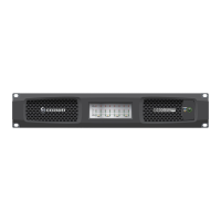
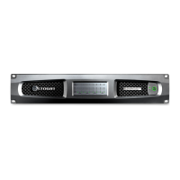
DCi 2|300N
DCi 4|300N
DCi 8|300N
DCi 2|600N
DCi 4|600N
DCi 8|600N
DCi Series – Network Input Models
Operation Manual
5032774 - 08/13

Questions and Answers:

Crown DCi 4|300N Specifications

General IconGeneral
Channels4
Power per channel @ 4 ohms300 W
Power per channel @ 8 ohms150 W
Power per channel @ 70V300 W
Power per channel @ 100V300 W
Signal to Noise Ratio> 100 dB
Input Sensitivity1.4 V
Gain32 dB
Frequency Response20Hz - 20kHz
CoolingConvection
Dimensions19" x 3.5"
Power Requirements100V-240V~50/60Hz
Input Impedance20kΩ balanced, 10kΩ unbalanced

Summary

Important Safety Instructions

Declaration of Conformity

Welcome

Product Installation

Unpacking and Inspection

Unpack amplifier, inspect for damage, and prepare for installation.

Amplifier Mounting and Cooling

Mounting the amplifier in a rack or on a surface and ensuring proper airflow.

Front Panel Interface

Front Panel Indicators and Controls

Explains front panel LEDs (Fault, Thermal, Clip, Signal, Ready) and the Power Button.

Back Panel Connectivity

Back Panel Connectors and Power

Details AC Power Inlet, Fuse, Output Connectors, and Cooling Fan Outlet.

Back Panel Network and Control Ports

Describes Ethernet, BLU Link, Auxiliary Connector, and GPIO ports.

System Setup and Configuration

Wiring Input and Output Connectors

Instructions for connecting input and output wiring using appropriate gauges.

System Setup and Configuration

Connecting Loudspeakers and Load Setup

Determining load impedances and configuring speakers for proper operation.

Network Configuration using NetSetter

NetSetter Software Overview

Introduction to NetSetter software and its main interface elements.

NetSetter Grid Field Details

Detailed explanation of each field within the NetSetter grid for device configuration.

Audio Architect Operation Modes

Audio Architect Offline/Online Modes

Explains Offline and Online modes in Audio Architect for system configuration.

Matching Devices in Audio Architect

Describes how to associate amplifiers in the venue design with network devices.

Audio Architect Device Management

Managing Devices in Audio Architect

Dragging devices, editing properties, and understanding online/offline modes.

Amplifier Mode Configuration

Hi-Z and Low-Z Output Configuration

Setting individual channels for High-Z or Low-Z operation.

Input Cascading

Input Cascading Setup

How to cascade analog inputs for flexible output driving.

Bridge Mono Output Operation

Bridge Mode Configuration

How to bridge amplifier outputs for increased power.

Low-Z Output Configuration

Low-Z Output Wiring

Typical input/output wiring for low-impedance loads.

Bridge Mode Output Configuration

Bridge Mode Wiring

Wiring for 16, 8, or 4 Ohm bridge mode operation.

Dual Hi-Z (70V/100V) Configuration

70V/100V Operation Wiring

Wiring for dual high-impedance (70V/100V) operation.

Bridge Mode Hi-Z Configuration

140V/200V Operation Wiring

Wiring for bridged high-impedance (140V/200V) operation.

AC Mains Connection

Amplifier Startup Procedure

Step-by-step guide for powering on the amplifier for the first time.

General Operational Safety Precautions

GPIO Control Port

GPIO Port Hardware Specs

Details pinout and electrical specifications for the GPIO port.

GPIO Input Configuration

Setting up inputs for control functions using Audio Architect.

GPIO Software Control Parameters

Available software parameters for controlling GPIO functions.

GPIO Control Port Configuration

Assigning State Variables to GPIO

How to assign state variables to control port inputs in Audio Architect.

GPIO Control Port Outputs

GPIO Output Mode Configuration

Setting output modes (Manual, Report Errors, Report Online Status) and polarity.

Auxiliary Port Functions

Aux Port Sleep Mode Function

Connecting pins to put the amplifier into sleep mode.

Aux Port Status Monitoring

Using the Aux port for basic amplifier monitoring.

BLU Link Audio Bus Operation

BLU Link Specifications

Technical details on BLU Link, including channels, speed, and bus type.

BLU Link Hardware and Fault Tolerance

Connecting BLU Link devices in a loop for redundancy and fault tolerance.

BLU Link Mastership and Clocking

How mastership is determined and clock synchronization within a BLU Link network.

BLU Link Operation Details

BLU Link LED Indicators

Explains the status indicated by the BLU Link port LEDs.

BLU Link Audio Routing

How to route audio signals to and from BLU Link devices.

BLU Link Routing Configuration

BLU Link Input/Output Assignment

Configuring input and output channel assignments for BLU Link streams.

BLU Link Latency and Settings

BLU Link Output Configuration

Setting up BLU Link outputs as on-ramps for digital audio.

BLU Link Latency Information

Details latency for various BLU Link audio paths.

Advanced Operation: DSP Features

Presets and Speaker Tunings

Overview of DSP presets and speaker tuning capabilities.

Creating User Presets

Steps for creating and saving custom DSP presets.

Advanced Operation: Signal Path

DCi Signal Path Overview

Diagram and explanation of the amplifier's internal signal processing path.

Advanced Operation: Speaker Tunings

Basic Speaker Tuning Panel Functions

Basic functions of the Speaker Tuning Panel for recalling and storing tunings.

Advanced Operation: Speaker Tuning Panel

Advanced Speaker Tuning Functions

Accessing advanced STP functions for parameter modification.

Speaker Tuning Libraries Management

Managing speaker tuning libraries within Audio Architect.

Advanced Operation: Library Management

Speaker Tuning Library Management

Covers library types, loading, saving, locations, and naming conventions.

Advanced Operation: Onboard DSP

Software DSP Control

How to use Audio Architect to control onboard DSP for various applications.

DSP Control Interface Overview

Navigating the DSP control panels within Audio Architect.

Advanced Operation: Signal Monitoring

Input/Output Signal Level Meters

Understanding the green input and blue output signal level meters.

Front Panel Indicator Interpretation

Explains the meaning of various front panel LEDs like Temp, Limit, Load, Ready, and Fault.

Advanced Operation: Input Routing

Input Signal Router Configuration

Selecting and routing audio sources (Analog, BLU Link) to amplifier channels.

Signal Routing Modes Explained

Details on Analog, BLU Link, Analog Backup, and Analog Override routing modes.

Advanced Operation: Source Routing

Quick Start Source Routing

Using predefined quick start options for input source routing.

Manual Source Routing Parameters

Adjusting Threshold, Attack, Release, and Depth of Cut for priority routing.

Advanced Operation: Delay and EQ

Input Delay and Driver Alignment

Setting input delay up to 2 seconds and output delay for driver alignment.

Input/Output Equalization

Adjusting channel equalization with up to 8 frequencies and various filter types.

Advanced Operation: Crossover Filters

Crossover Filter Configuration

Using IIR crossover filters with multiple filter types and gain adjustments.

Advanced Operation: Limiters

LevelMax Suite Overview

Introduction to the peak voltage, RMS, clip, and thermal limiters.

Limiter Mode and Parameter Adjustment

Configuring automatic or advanced modes for limiters and their parameters.

Per Channel Settings

Channel Input Attenuator Adjustment

Using the 21-position detented input attenuator for level control.

Amplifier Protection System

Thermal and Fault Protections

Details on thermal limits, fault conditions, and AC voltage protection.

System Component Protections

Information on fuse protection, cooling systems, and the universal power supply.

Troubleshooting Guide

Troubleshooting Power Indicator Issues

Diagnosing problems related to the power indicator being off or flashing.

Troubleshooting Thermal/Fault Indicators

Identifying and resolving issues indicated by thermal or fault LEDs.

Troubleshooting Audio Issues

Diagnosing Distorted Sound

Common causes and solutions for distorted audio output.

Resolving No Sound Issues

Steps to take when there is no audio output from the amplifier.

Troubleshooting Signal and Status

Troubleshooting No Input Signal

Identifying why there might be no input signal detected.

Bridge Mode LED Interpretation

Understanding the status of the Bridge LED indicator.

DCi Specifications

Power Output Specifications

Detailed power output ratings for dual-mode and bridge mono configurations.

Gain and Sensitivity Specifications

Voltage gain and input sensitivity ratings for different impedance loads.

DCi Specifications Overview

Physical Dimensions

Width, height, and depth measurements for each DCi model.

Performance Specifications Details

Comprehensive performance metrics including frequency response and distortion.

AC Power Draw and Thermal Dissipation (DCi 2-Series)

DCi 2|300N Power Data

Power draw and heat dissipation for the DCi 2|300N model.

DCi 2|600N Power Data

Power draw and heat dissipation for the DCi 2|600N model.

AC Power Draw and Thermal Dissipation (DCi 4-Series)

DCi 4|300N Power Data

Power draw and heat dissipation for the DCi 4|300N model.

DCi 4|600N Power Data

Power draw and heat dissipation for the DCi 4|600N model.

AC Power Draw and Thermal Dissipation (DCi 8-Series)

DCi 8|300N Power Data

Power draw and heat dissipation for the DCi 8|300N model.

DCi 8|600N Power Data

Power draw and heat dissipation for the DCi 8|600N model.

Service and Repair Information

Contacting Crown for Service

Information on contacting technical support and authorized service centers.

Shipping for Factory Service

Instructions for packaging and shipping the unit for factory repair.

Service Procedures

Packing Instructions

Detailed guidelines for securely packing the product for shipment.

Non-Warranty Repair Payment

Procedures for payment of repairs not covered by warranty.

Warranty Information

Warranty Coverage and Exclusions

Details the warranty period, coverage, and items excluded from warranty.

Legal Disclaimers and Terms

Covers consequential damages, warranty alterations, and design changes.

Product Registration

Related product manuals