3–7
Operation
3.7 RF Output Control
Set this control for the desired output power level. Preferably, set the power with
an external RF wattmeter connected in the coaxial line to the antenna. You may
also use the RF power reading on the digital multimeter.
The control sets the RF output voltage. Actual RF output power varies as the
approximate square of the relative setting of the control. For example, a setting of
“50” is approximately 1/4 full power.
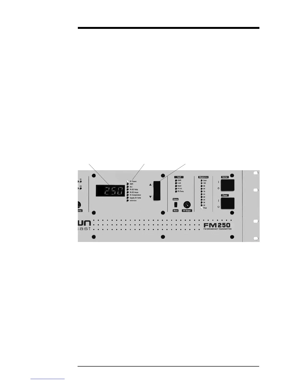
3.8 Digital Multimeter
The four-digit numeric display in the center of the front panel provides informa-
tion on transmitter operation. Use the “Up” and “down” push-buttons to select
one of the following parameters. A green LED indicates the one selected.
Illustration 3–5 Digital Multimeter
RF Power—Actually reads RF voltage squared, so the accuracy can be affected by
VSWR (RF voltage-to-current ratio). See section 5.4 for calibration. Requires
calibration with the RF reflectometer being used.
SWR—Direct reading of the antenna standing-wave ratio (the ratio of the desired
load impedance, 50 ohms, to actual load).
ALC—DC gain control bias used to regulate PA supply voltage. With the PA power
supply at full output voltage, ALC will read about 6.0 volts. When the RF output is
being regulated by the RF power control circuit, this voltage will be reduced,
typically reading 4 to 5.5 volts. The ALC voltage will be reduced during PA DC
overcurrent, SWR, or LOCK fault conditions.
Multimeter Multimeter Functions Multimeter Push-buttons
 Loading...