4–3
Principles of Operation
4.2 Audio Processor Circuit Board
The audio processor board provides the audio control functions of a compressor,
limiter, and expander. Illustration 6–5 and accompanying schematic may be useful
to you during this discussion.
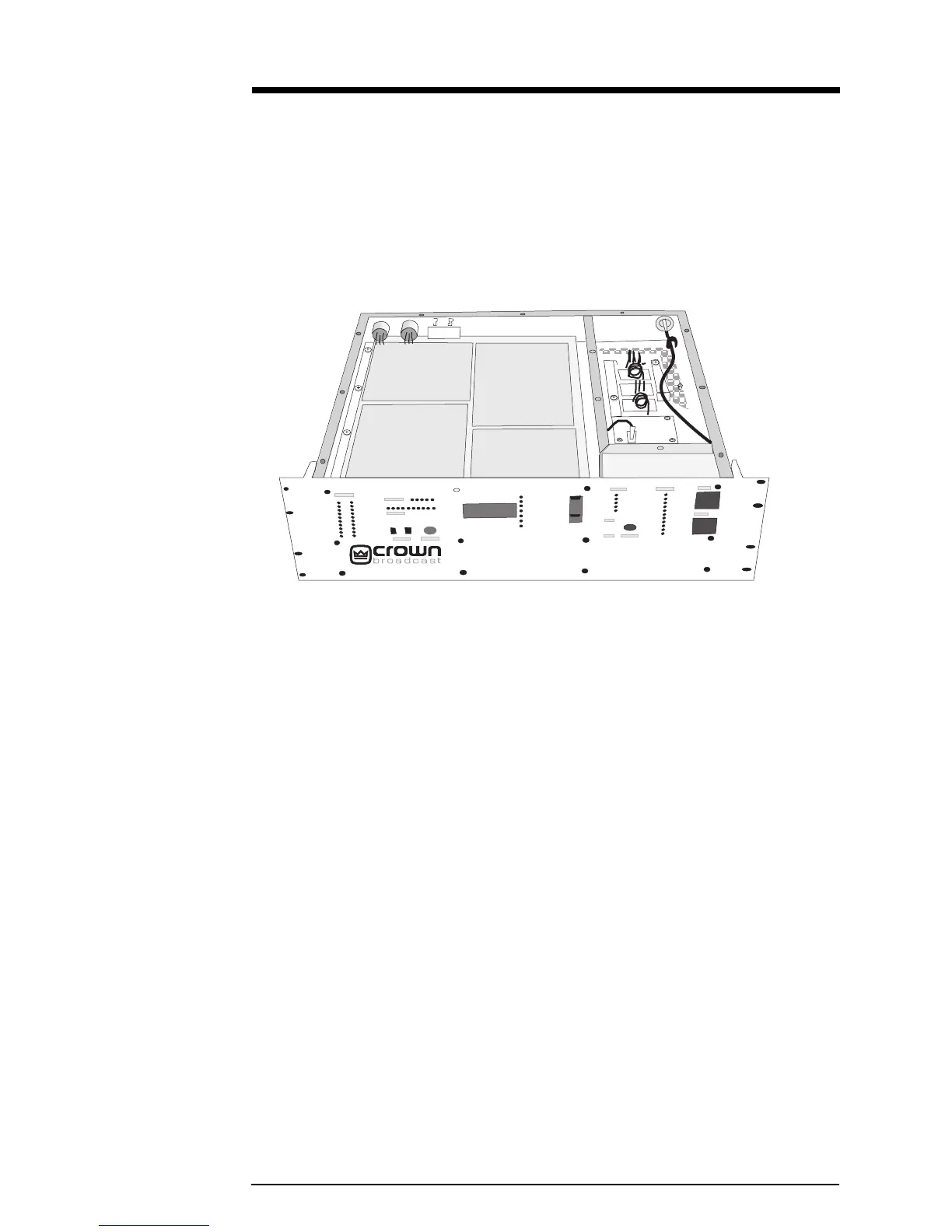
Audio
Processor
Board
Illustration 4–2 Audio Processor Board
This board also contains the pre-emphasis networks. Reference numbers are for the
left channel. Where there is a right-channel counterpart, references are in
parenthesis. One processor circuit, the eighth-order elliptical filter, is located on
the stereo generator board.
Audio input from the XLR connector on the rear panel of the transmitter goes to
differential-input amplifier, U1A (U2A).
Binary data on the +6 dB and +12 dB control lines sets the gain of inverting
amplifier U1B (U2B). Analog switch, U3, selects one of four feedback points in 6–dB
steps.
The output of U1B (U2B) goes to an eighth-order, elliptical, switched-capacitor,
low-pass, 15.2–kHz filter. The filter finds its home on the stereo generator board to
take advantage of the ground plane and proximity to the 1.52 MHz clock.
The circuit associated with U4B (U4A), along with R22/C8 (R58/C20), form
third-order, low-pass filtering, attenuating audio products below 30 Hz.
The output level of analog multiplier U5 (U6) is the product of the audio signal at
pin 13 and the DC voltage difference between pins 7 and 9. At full gain (no gain
reduction) this difference will be 10 volts DC.
FM250
 Loading...