4–6
FM30/FM100/FM250 User's Manual
i
n
q
u
e
s
t
o
m
o
n
d
o
,
f
o
r
s
e
,
u
n
o
s
i
d
i
c
e
s
e
d
i
c
i
a
m
o
c
h
e
m
a
s
c
r
i
v
e
n
d
o
c
o
n
i
n
q
u
e
s
t
o
m
o
n
d
o
,
f
o
r
s
e
,
u
n
o
s
i
d
i
c
e
s
e
d
i
c
i
a
m
o
c
h
e
m
a
s
c
r
i
v
e
n
d
o
c
o
n
m
a
s
c
r
i
v
e
n
d
o
c
o
n
i
n
q
u
e
s
t
o
m
o
n
d
o
,
f
o
r
s
e
,
u
n
o
s
i
d
i
c
e
s
e
d
i
c
i
a
m
o
c
h
e
m
a
s
c
r
i
v
e
n
d
o
c
o
n
m
a
s
c
r
i
v
e
n
d
o
c
o
n
in
q
u
e
s
t
o
m
o
n
d
o
,
f
o
r
s
e
,
u
n
o
s
i
d
i
c
e
s
e
d
i
ci
a
m
o
c
h
e
m
a
s
c
r
i
v
e
n
d
o
c
o
n
s
e
d
i
c
i
a
m
o
c
h
e
m
a
s
c
r
i
v
e
n
d
o
c
o
n
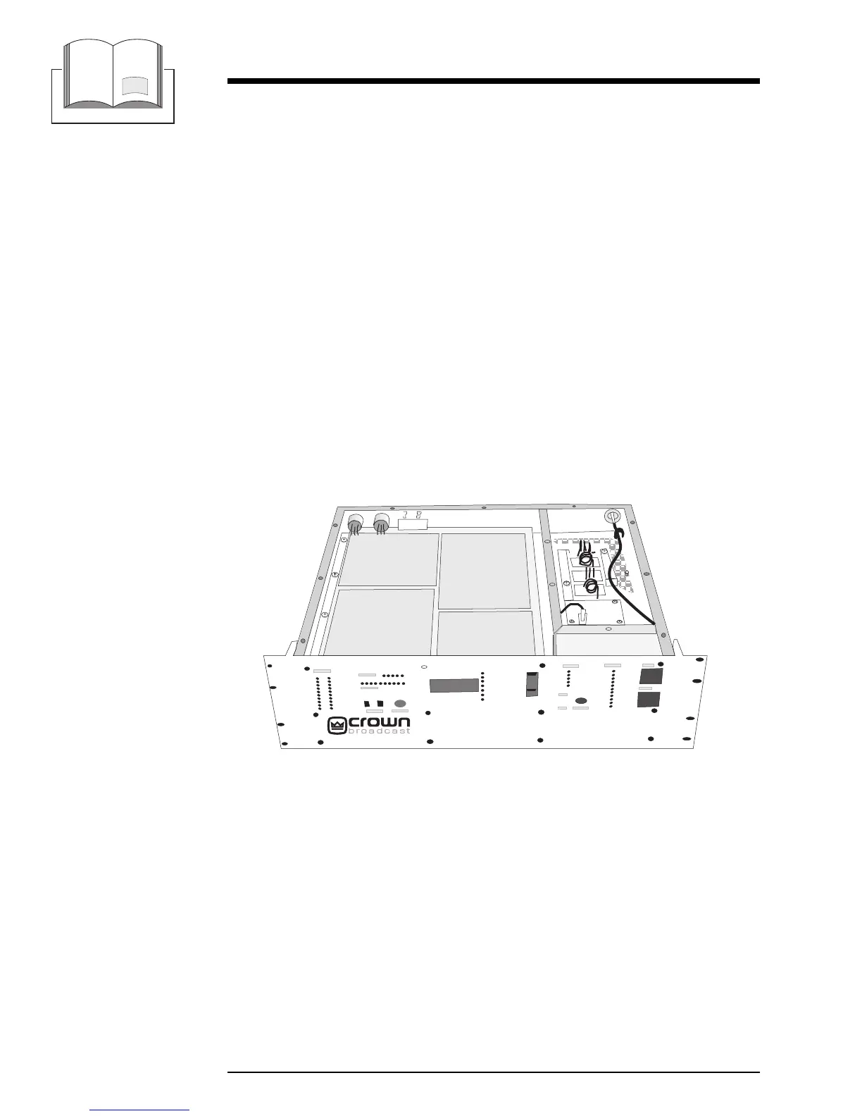
4.4 RF Exciter Circuit Board
This board is also known as the Frequency Synthesizer board. The entire
component side of the board is a ground plane. Frequency selector switches along
the front edge of the board establish the operating frequency. The VCO
(voltage-controlled oscillator) circuitry is inside an aluminum case.
Illustration 6–7 and accompanying schematic can be used as reference in this
discussion.
VCO61 operates at the synthesizer output frequency of 87 MHz to 108 MHz.
The frequency is controlled by a voltage applied to pin 8 of the VCO.
A sample of the RF comes from A2 and is fed to the PLL chip U6.
U304 is a phase-locked-loop frequency synthesizer IC. The 10.24 MHz from the
crystal oscillator is divided to 10 kHz. Internal programmable dividers divide the
87 - 108 MHz RF to 10 kHz. Differences between the two signals produce error
FM250
®
RF
Exciter
Board
 Loading...