6–2
FM30/FM100/FM250 User's Manual
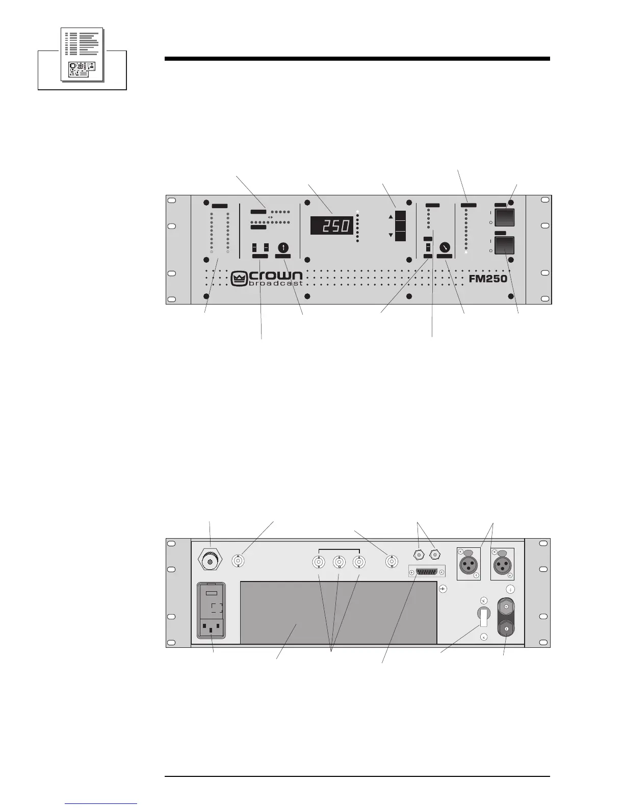
6.1 Views
Illustration 6–1 Front ViewIllustration 6–1 Front View
Illustration 6–1 Front ViewIllustration 6–1 Front View
Illustration 6–1 Front View
Illustration 6–2 Rear ViewIllustration 6–2 Rear View
Illustration 6–2 Rear ViewIllustration 6–2 Rear View
Illustration 6–2 Rear View
Power
Carrier
Modulation
Fault
Stereo
Mono RF OutputProcessingInput Gain
Wide Band
High Band
Audio Input
High
Low
2
-6
-12
-18
2
+6 dB
+12 dB
10
20
Expand
Compress
RF Power
SWR
ALC
PA DC Volts
PA DC Amps
PA Temperature
Supply DC Volts
Voltmeter
SWR
Lock
Input
PA DC
PA Temp
Over
100
90
80
70
60
50
40
30
20
Pilot
FM BROADCAST TRANSMITTER
Power Switch
Carrier SwitchDigital Multimeter Multimeter Select
Stereo/Mono
Switch
Processing Control
Fault Indicators
Modulation
Indicators
Audio Processor
Input Level
Indicators
Relative RF
Voltage Out
Gain
Reduction/Expansion
Indicators
Input Gain
Switches
OFF
SCA IN
COMPOSITE IN
MONITOR
R
L
23
REMOTE I/O
RIGHT
LEFT/MONO
B
A
T
T
E
R
Y
36 VDC
+
CIRCUIT
BREAKER
1
FUSE
RF Output
RF Output Monitor
SCA Inputs
AC Power In
DC Power In
DC Circuit
Breaker
Remote I/O
Audio Inputs
Audio Monitors
Composite
Input
Power Amplifier
and Cooling
(FM100 and FM 250 only)