17
L510032-16
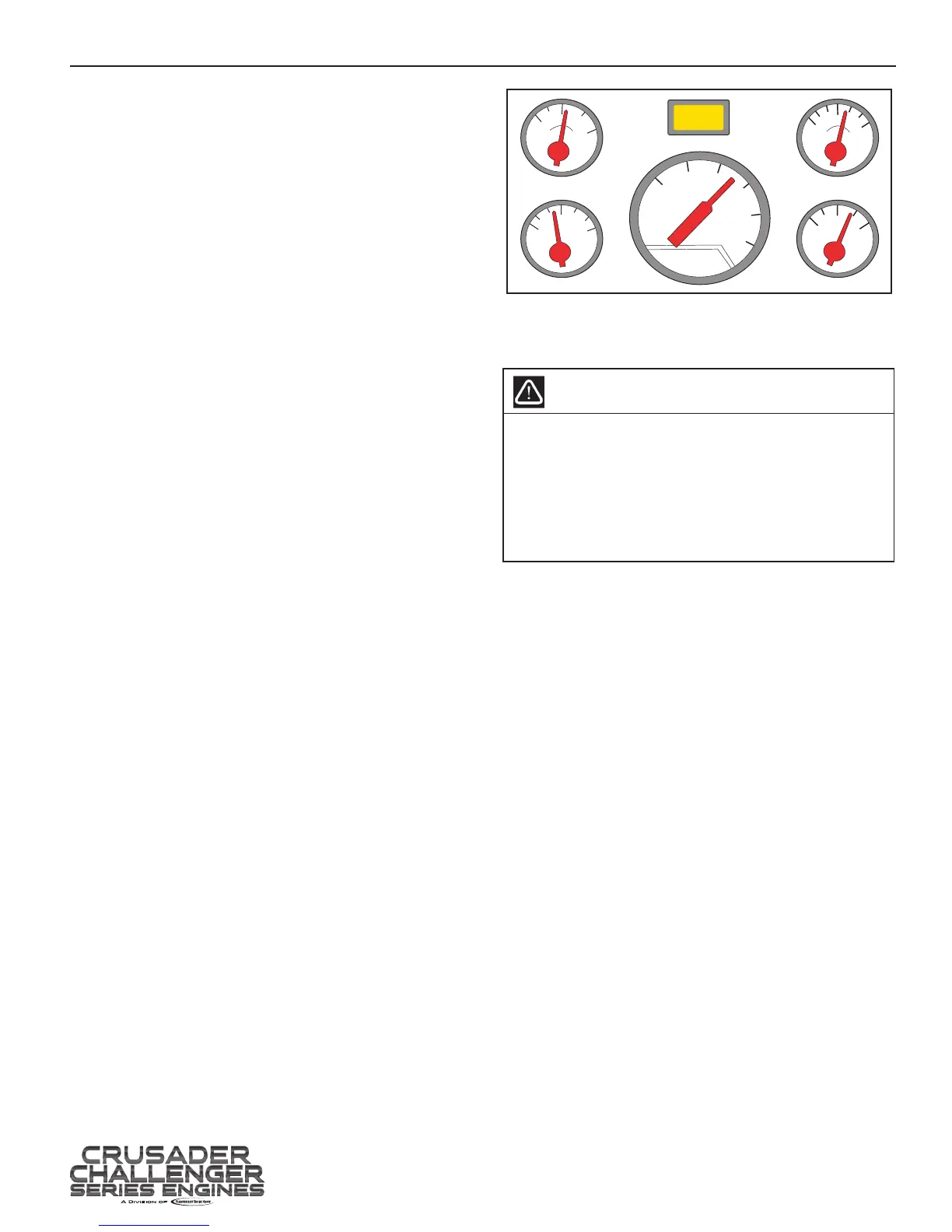
INSTRUMENTATION
Boat manufacturers install many dierent types of
instrumentation on boats. Become familiar with the
instrumentation on your boat and be aware of abnormal
operating conditions. The following is a brief explanation
of typical instrumentation found on most boats:
1. Tachometer - indicates the engine RPM
(revolutions per minute)
2. Water Temperature Gauge - indicates the engine
coolant temperature
3. Oil Pressure Gauge - indicates the engine oil
pressure
4. Voltmeter - indicates the battery voltage and
charging system voltage
5. Hour Meter - indicates the engine operating time
6. Fuel Level Gauge - indicates the fuel tank level
7. Malfunction Indicator Lamp (MIL) and Check
Gauges Lamp (CGL) - indicates a possible
problem with the engine control system or engine
Notice: Many boat manufacturers are using Controller
Area Network (CAN) based instrumentation. This
instrumentation is driven by a two-wire network from
the engine. Refer to your boat manufacturers Owner’s
manual for the type of instrumentation being used with
your application.
ELECTRONIC SPEED CONTROL (IF EQUIPPED)
This engine is equipped with a Digital Throttle Control
(DTC) system. The system may use a throttle cable
connected between the throttle handle and a Throttle
Control Positioning (TCP) sensor located on the engine.
Most applications have the TCP sensor located in the
throttle handle and there is NO throttle cable going to the
engine. The Throttle Control Positioning sensor provides
throttle position information to the engine management
system which, in turn, electronically controls engine
throttle movement.
This boat may also be equipped with an electronic
speed control system for skiing, wake boarding, or cruise
control. When the boat is operated in a speed control
mode, the operator may not have full control of the
throttle until the speed control system is deactivated.
Example: If the speed control system is engaged at 32
mph, the throttle handle may be “dead” when trying to
accelerate above 32 mph. The speed control system
would need to be disengaged, then the operator will gain
full control of the boat speed.
Refer to your Boat Manufacturers Owners/Operation
manual for specic operation and troubleshooting
information for your speed control system.
OPERATING INSTRUCTIONS - 5
CHECK
ENGINE
TACH
0
10
20
30
60
50
40
E
FUEL
1/2
F
TEMP
200
170
100
80
40
0
OIL
VOLT
10
16
13
Figure 5-1 Typical Gauge Style Instrument Panel
STARTING ENGINE (FUEL INJECTED ENGINES)
WARNING
Before starting engine, ventilate the engine
compartment by operating the bilge blower for
a minimum of ve minutes to remove any gas
fumes from the engine compartment. If the boat
is not equipped with a blower, open the engine
compartment hatches to ventilate and leave open
while starting engine.
IMPORTANT: Do not start the engine without water
being supplied to the sea water pick-up pump or
sea-water pump impeller will be damaged, and
subsequent overheating damage to the engine may
result.
IMPORTANT: The following items should be
checked before starting the engine, and each time
the boat is operated:
• Fuel system for any signs of leakage
• Operation of remote controls and steering
• Engine and transmission oil levels
• Fuel tank levels
• Exhaust system for leaks and tightness of the
clamps
• Battery connections and water level in battery
cells
• Accessory drive belt(s)
 Loading...