5 V4-02-2011
INSTALLATION DESCRIPTION
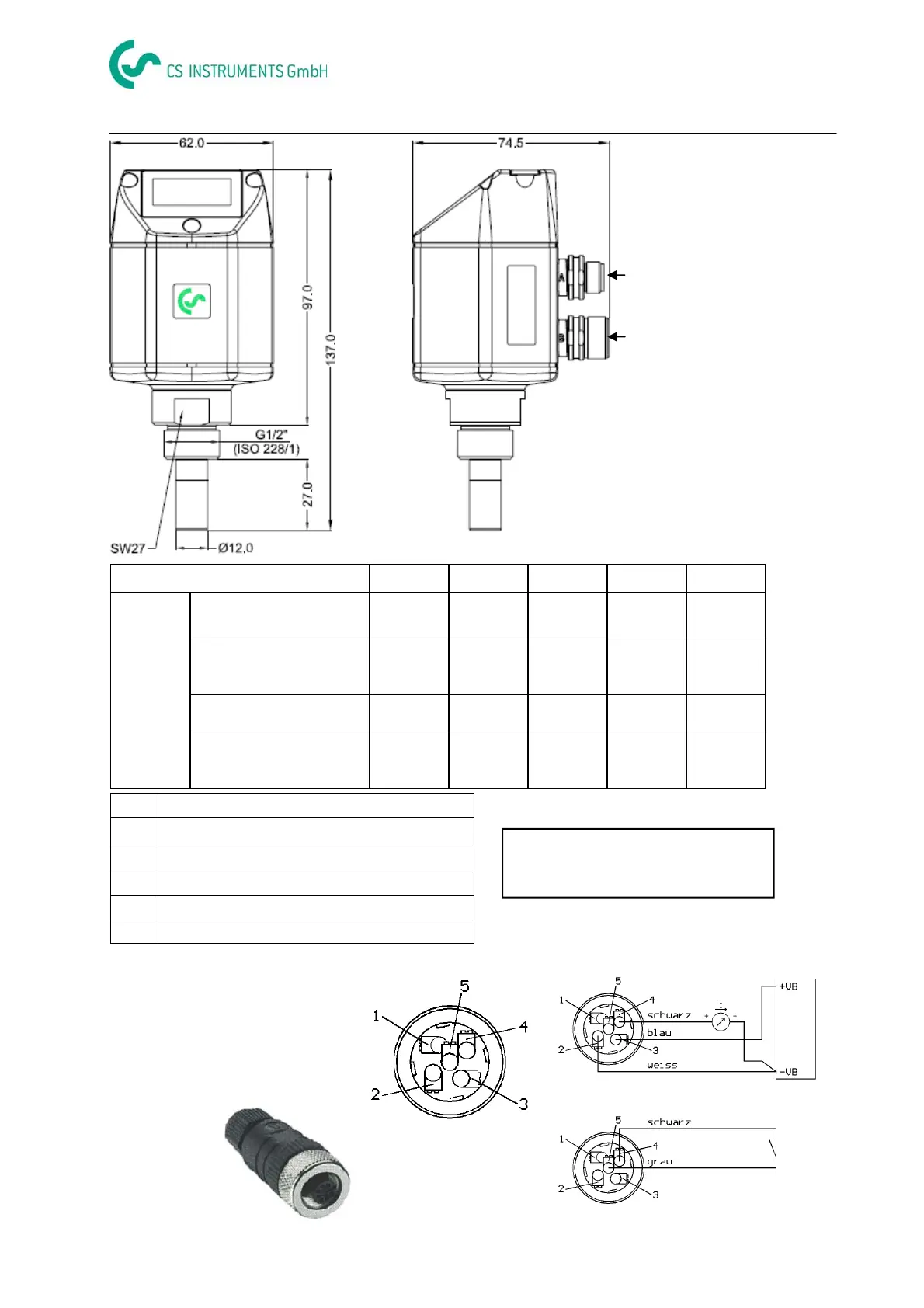
Connector plug A (signal
and supply)
Connector plug B (alarm)
M12 Connector plug A/B
Pin 1 Pin 2 Pin 3 Pin 4 Pin 5
FA 400
Connector plug A
SDI -VB +VB +I
4...20 mA
NC
Connection cable A
0554.0104 (5 m)
0554.0105 (10 m)
brown white blue black grey
Connector plug B
NC NC NC REL REL
Connection cable B
0554.0106 (5 m)
0554.0107 (10 m)
NC NC NC black grey
SDI Digital Signal (internal data transfer)
-VB Negative supply voltage 0 V
+VB Positive supply voltage 16...30 VDC smoothed
+I Positive 4...20 mA signal
NC Not connected
REL Relay output
Connector plug
Connector plug A :
Connector plug B :
FA 400: Relay NO (60 V, 0.5 A)
Relay opens in case of alarm
and power failure
If no connection cable ( 0553 0104, 0553
0105 ) is ordered the sensor will be sup-
plied with a M12 connector plug. the user
can connect the supply and signal cables
as indicated in the connection diagram.