Connectors
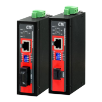
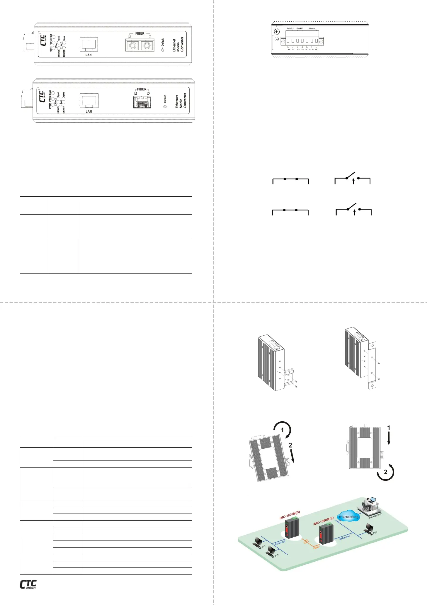
Figure 1. IMC-1000M-(E) Front Panel
Figure 2. IMC-1000MS-(E) Front Panel
IMC-1000M(-E) has fixed optical transceiver options for connector
types of ST or SC while the IMC-1000MS(-E) model uses industry
standard SFP modules. The LAN connection uses a shielded RJ-45
which supports Auto MDI/MDI-X. Configuration settings are
accomplished via Web based management. Please see page 4 for
web setup information.
‘Default’ Push Button
The ‘Default’ push-button provides the following two functions:
Using a ball-point pen, press the ‘Default’
button and hold for 3~8 seconds then
release. The converter will clear all
unsaved settings and will be restarted.
Return
to
factory
defaults
Using a ball-point pen, press the ‘Default’
button and hold for 10 seconds (or longer)
then release. DO NOT POWER OFF and
allow the device to again fully reboot
(about 25 seconds). Then, all factory
defaults have been returned.
Special Features
1. LFP: Link Fault Pass through allows a link condition to be passed
from fiber to TP or from TP to fiber.
2. Mode: Normally, this device acts as a store & forward switch
device supporting MAC learning and filtering. In converter mode, the
internal switch is bypassed, enabling low latency and support for
unlimited frame size. Do not enable LFP in converter mode or fiber
may not link.
NOTE: LAN and Fiber speed must match when configured in converter mode. If
fiber speed is 1000M, UTP speed must be 1000M.
3. 100/1000: This device supports dual rate fiber speed. Please
ensure that the SFP modules used in the IMC-1000MS(-E) are
capable of operating at the selected rate. The IMC-1000M(-E) with
fixed transceiver will operate at either forced optical rate.
For other advanced functions, please see the USER MANUAL.
LED Indicators
Power is connected and active at the
PWR1/PWR2 input terminal connection.
Fiber link loss, TP link loss or either one
power loss, depending on the alarm
programming in Web management.
Normal operation with no power, fiber
or TP faults.
Fiber port has optical link.
Blinking when there is data traffic.
The fiber connected speed is 100M.
The fiber connected speed is 1000M.
Blinking when there is Ethernet traffic.
The UTP (LAN) speed is 100M.
The UTP (LAN) speed is 1000M.
The UTP (LAN) speed is 10M.
Power & Alarm
Figure 3. Terminal Block
A removable terminal block on the top panel provides both power
and alarm connections. See below for explanations.
Power
There are input connectors for two power sources on the terminal
block. Only one power source is required for normal operation. The
second power source input may be provided for redundancy.
Alarm Relay Contact
The Alarm is one electrical relay that can be wired into an alarm
circuit and is triggered in the event of port link loss (optical or
electrical) or loss of either one power source. From the common pin
(COM), the relay can be connected as Normally Open (NO) or
Normally Closed (NC). When an alarm occurs NO-to-COM circuit
closes and the COM-to-NC circuit opens. See Figure 4 and 5 for
normal and fault illustration in each alarm relay type. Please note
that the alarm relay contact can only support 1A current at 24VDC.
Do not apply voltage and current that exceed these specifications.
Web Operation
IMC-1000M(-E) & IMC-1000MS(-E) can be configured through an
easy-to-use point and click graphical user interface (GUI) by using
any standard Web browser. The device comes from the factory with
the following TCP/IP settings and login information:
Installation
The converter comes with both wall mount and DIN rail hardware
brackets. When installing the DIN rail bracket, be sure to correctly
align the orientation pin.
Figure 6. DIN Rail Figure 7. Wall Mount
The converter with DIN Rail bracket has a steel spring in the upper
rail of the bracket. This spring is compressed for mounting and un-
mounting by applying downward force.
Figure 8. Mounting Figure 9. Un-mounting
Application
Username: admin
Password: admin
IP address: 10.1.1.1
Subnet Mask: 255.255.255.0
Gateway: 10.1.1.254
Figure 10. IMC-1000M(-E) & IMC-1000MS(-E) Ethernet Transmission
Figure 4. Alarm Relay for NO (Normally Open) Type
Figure 5. Alarm Relay for NC (Normally Closed) Type
 Loading...