EasyManua.ls Logo

CTC Union FIB1-10/100 series - User Manual

CTC Union FIB1-10/100 series
2 pages
To Next Page IconTo Next Page
Loading...
Specifications
Standard
IEEE802.3 10BASE-T, IEEE802.3u 100BASE-TX, l00BASE-FX (Fast Fiber, 100Mbps)
Supports Full Duplex Ethernet mode (200Mbps)
FIB1-10/100 family supports transmission of Ethernet packet up to 1600 Bytes in size.
10/100BASE-TX RJ-45 Connectors
One RJ-45 connector is provided auto MDI/X function for connection to either MDI-X (To PC) or MDI (To HUB)
equipment. This allows all UTP connections to be made using only a common straight-through UTP cable.
RJ-45 Pin
MDI type
1 Tx+
2 Tx-
3 Rx+
6 Rx-
Installation Instructions for
FIB1-10/100 Family 10/100BASE-TX / 100BASE-FX
Fiber Transceiver Converters
Description
The FIB1 Family are standalone fiber media converters available in a number of different models that also act as line
cards for placement in the FRM301 Platform Media Converter Chassis. The FIB1-10/100 is a media converter for
10Base-T or 100Base-TX, data transmission over optical fiber media depending on your specific network needs. .
All media converters are available with either multi-mode or single-mode optical transceivers and with connectors
for SC, ST or FC. In single mode, WDM (Wave Division Multiplexing with SC connector) is also available in 20 or
40KM reach, which will provide the ability to transmit and receive data using only a single optical fiber. When the
FIB1-10/100 card is placed in the FRM301 rack with SNMP management, the card status, type, version, fiber link
status, data link status and alarms can all be displayed. For the UTP side, auto-negotiation is default. These units will
automatically tailor themselves to convert both half-duplex or full-duplex signals and You may also set the FX side
in full-duplex only or half-duplex only. The Fiber Transceiver Converters give you the freedom to extend your
10/100Mbps cabling distance by allowing connectivity up to 120 kilometers. Six LED indicators signal the power
status of the converter, UTP port speed, duplex status and Link/RX and FX port Link/RX and duplex status.
Fiber Connections
Ethernet Connections
DC Jack
LEDs
DIP Switches
10/100BASE-TX UTP Cable
Cable type: 10Base-T; Cat. 3,4 or 5 ; 100Base-Tx; Category 5
Maximum cable distance: 100 meters (328 feet)
1.Full /Half : The Fiber Duplex will be configured in Full-duplex or Half-duplex
* This switch has included an “Auto Reset” function so the power-reset is not
necessary when any modification is made here.
2. Loop-back test and get remote side status ( NORM ÆNot active ; LBT ONÆactive )
* If the Local side loop-back test is active then LEDs (except the PWR LED) will
all blink rapidly and refresh to display the remote side status.
**Note:
This application must be run under the circumstance that the remote side
loop-back testing function is off.
Fiber Optic Connectors
For FIB1-10/100: Two connectors are provided for fiber optic cable connection.
One is for transmission and the other is for reception of optical data
For FIB1-10/100W: One connector is provided for fiber optic cable connection.
For both transmission and reception of optical data.
Please note that transceiver “A must connect to transceiver
“B” for proper fiber linking.
Environment
Temperature : 0 -70
Humidity 10-90% non condensing
Dimension
122.6mm x 85.6mm x 20mm
(H x W x D)
Power
+9V /1A maximum
DC Plug Type : Center Positive
LED Function State Status
PWR Power indicator On Converter has power
Off Converter has no power
Fiber Full Mode display On Fiber side full duplex mode (200mbps)
Off Fiber side half-duplex mode
Fiber Link Fiber link On The fiber link is ok.
Off No link or the link is faulty.
Blinking Receiving data on the fiber.
LAN 100 Mode display On UTP side is operating in 100Mbps mode.
Off UTP side is operating in 10Mbps mode
LAN Full Mode display On UTP side full duplex mode (200mbps).
Off UTP side half-duplex mode
LAN Link Ethernet link On The UTP link is ok.
Off No link or the link is faulty.
Blinking Receiving data on Ethernet.
Front Panel DIP Switch Setting
LED Indicators
V.: 1.4
Question and Answer IconNeed help?

Do you have a question about the CTC Union FIB1-10/100 series and is the answer not in the manual?

CTC Union FIB1-10/100 series Specifications

General IconGeneral
Operating Temperature0°C to 50°C
Type10/100Base-TX to 100Base-FX
Ports1 x RJ-45, 1 x Fiber
Fiber Port100Base-FX
TP Port10/100Base-TX
Fiber ConnectorSC, ST
Fiber DistanceVaries by model (2km, 20km, 40km, etc.)
Wavelength1310nm/1550nm (single-mode)
StandardsIEEE 802.3u
Power Input5V DC, 1A
DIP-SwitchesYes
InterfaceRJ-45, Fiber
Fiber TypeMulti-mode/Single-mode
Transfer DistanceUp to 120km (Single Mode, varies by model)
ConnectorRJ-45, SC/ST
Humidity5% ~ 90% RH, Non-condensing
Power SupplyExternal

Summary

Product Description

Specifications Overview

Supported Standards

Details the IEEE standards supported by the converters for Ethernet and fiber connections.

RJ-45 Connector Features

Describes the auto MDI/X function for UTP connections to various network devices.

Environmental Requirements

Specifies the operating temperature and humidity ranges for the device.

UTP Cable Specifications

Defines the UTP cable type and maximum transmission distance.

Physical Dimensions

Provides the physical dimensions (Height x Width x Depth) of the media converter.

Power Requirements

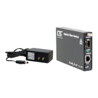
Details the required DC input voltage and maximum current for power.

Fiber Optic Connector Details

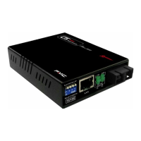
Explains the fiber optic connectors for transmission and reception.

Front Panel Controls and Indicators

DIP Switch Settings

Overview of front panel DIP switches for configuration.

LED Indicator Functions

Details the status and meaning of each LED indicator on the front panel.

Detailed DIP Switch Configuration

UTP Auto;Manual Mode

Configures UTP port for automatic or manual speed and duplex settings.

UTP Duplex Mode Selection

Sets the UTP port to operate in either full-duplex or half-duplex mode.

UTP Speed Selection (100;10)

Forces the UTP port to operate at 100Mbps or 10Mbps speed.

Link-Loss-Forwarding Function

Enables indirect sensing of Fiber Link Loss via the UTP connection.

Installation and Connections

Installation Steps

Guidance on connecting the fiber interface cable and UTP Ethernet connection.

Connection Examples

Illustrations showing typical connection schemes for various network setups.

Advanced Features

Loop-back Testing (LBT)

Feature to confirm fiber or Ethernet circuit completion by sending test patterns.

Get CPE Status

Monitors remote side status including link, duplex, speed, and power.

Link-Loss-Forwarding (LLF)

Disables UTP transmitter upon Fiber Link Loss to report condition.

Compliance and Warnings

Trademarks

Lists registered trademarks for Ethernet and ST connectors.

FCC Compliance Warning

States compliance with FCC rules for commercial environments.

CISPR PUB.22 Class A

Notes compliance with EMC directive and European technical standards.

Class A Product Warning

Warns that Class A products may cause radio interference in domestic settings.

CE Notice

Indicates compliance with European Community EMC directive.

Related product manuals