Do you have a question about the CTC Union IMC-1000C and is the answer not in the manual?
Introduction to compact Gigabit Ethernet media converters for industrial use.
List of components provided with the IMC-1000C/IMC-1000CS devices.
Highlights of the media converters' capabilities and design.
Specifications for both electrical Ethernet and optical fiber port types.
Input power requirements, consumption, dimensions, and mounting.
Operating conditions, storage, humidity, and compliance certifications.
Mean Time Between Failures data based on MIL-HDBK-217.
Labeling and identification of physical ports and indicators on the device panels.
Description of the physical fiber and LAN ports and their functionality.
Explanation of the settings and functions controlled by the DIP switches.
Instructions for connecting the power supply and establishing earth ground.
Meaning of the status indicated by each LED on the device.
Guidance on how to install the device using DIN rail or optional wall mounting.
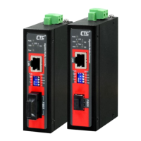
The IMC-1000C(-E) and IMC-1000CS(-E) are compact Gigabit Ethernet media converters designed for robust performance in demanding industrial environments. These devices facilitate the conversion between electrical 10/100/1000Base-T and optical 1000Base-X or 100/1000Base-X SFP Ethernet. Their primary function is to extend network distances and provide fiber optic connectivity in settings where traditional copper cabling is insufficient or susceptible to interference.
One of the key usage features of these converters is their adaptability to various installation scenarios. They are housed in rugged enclosures that support both DIN rail and wall mounting, offering flexibility for deployment in diverse industrial setups. The compact size and fanless design contribute to their suitability for space-constrained applications and environments where minimal noise and dust accumulation are critical. The IP30 protection rating further enhances their durability, safeguarding against ingress of solid objects.
The IMC-1000C(-E) and IMC-1000CS(-E) are engineered to operate across a wide range of temperatures, with standard models supporting -10°C to 60°C and wide operating temperature range models (-20°C to 75°C). This broad temperature tolerance makes them ideal for applications in industrial networking, intelligent transportation systems (ITS), military, and utility markets where extreme environmental conditions are common.
For connectivity, the IMC-1000C(-E) models feature fixed optical transceivers with ST or SC connector types, supporting 1000Mbps. In contrast, the IMC-1000CS(-E) models offer greater flexibility with an SFP slot that accommodates 100/1000Mbps SFP modules, allowing users to select the appropriate fiber type and distance. Both series provide a shielded RJ-45 connector for the LAN connection, supporting 10/100/1000Base-T with auto MDI/MDI-X functionality, simplifying network integration.
A notable usage feature is the inclusion of a 4-pole DIP switch for configuration settings, allowing users to customize the operation mode. This includes options for switching mode or pass-through converter mode, enabling or disabling Link Fault Pass Through (LFP), and setting fiber duplex modes (auto or force). For the IMC-1000CS(-E) models, the DIP switch also allows for forcing fiber speed to either 1000Mbps or 100Mbps, providing granular control over network performance. The LFP feature is particularly useful for network troubleshooting, as it forces the LAN port (or Fiber port) link down if the Fiber port (or LAN port) link goes down, helping to identify link failures more quickly.
Maintenance features are designed for ease of use and reliability. The power input is flexible, accepting 12/24/48VDC (9.6~60VDC) or 24VAC (18~36VAC) via a removable 2-pin terminal block. This versatility in power input simplifies integration into existing power systems. The device also supports power input reverse polarity protection, which helps prevent damage from incorrect wiring, enhancing the longevity and reliability of the unit.
For enhanced safety and to mitigate electromagnetic interference (EMI), an earth ground connector is provided on the top panel. This allows for safe release of leakage electricity to the earth, protecting both the device and personnel. The installation process for the ground wire is straightforward, involving the attachment of a grounding screw to a ring or fork-type terminal of a grounding cable, which is then fastened to the device.
The front panel of the converters features a comprehensive set of LED indicators that provide immediate visual feedback on the device's status, aiding in monitoring and troubleshooting. The PWR LED indicates whether power is connected and active. The 1000 and 100 LEDs show the connected LAN speed (1000M or 100M, respectively) and blink to indicate Ethernet traffic. The Fiber LED indicates if the fiber link is up and active, and also blinks to show Ethernet traffic on the fiber link. These indicators are crucial for quickly assessing the operational status of the converter and diagnosing potential network issues without requiring specialized tools or software.
Installation is designed to be user-friendly. For DIN rail mounting, hardware brackets are provided, and the process involves compressing a steel spring in the upper rail of the bracket by applying downward force. For wall mounting, optional brackets are available and can be obtained from a sales representative. Proper alignment of the orientation pin is emphasized during bracket installation to ensure secure mounting.
In summary, the IMC-1000C(-E) and IMC-1000CS(-E) are robust, versatile, and easy-to-manage industrial media converters. Their design focuses on providing reliable fiber optic connectivity in harsh environments, with features that support flexible deployment, customizable operation, and straightforward maintenance through clear LED indicators and protective power and grounding mechanisms.
| Auto-Negotiation | Yes |
|---|---|
| Auto-MDI/MDI-X | Yes |
| Fiber Connector | SFP slot |
| MAC Address Table | 1K |
| Case | Metal |
| Type | Media Converter |
| Ports | 1 x RJ-45, 1 x SFP |
| Standards | IEEE 802.3, IEEE 802.3u |
| Fiber Type | Multi-mode/Single-mode |
| Fiber Distance | Varies with SFP module |
| Wavelength | 850nm, 1310nm, 1550nm (depending on SFP module) |
| Forward Rate | 1.488Mpps |
| Buffer Memory | 1 Mbit |
| LED Indicators | Power |
| Power Input | 5V DC |
| Power Consumption | 2.5W |
| Operating Temperature | 0°C ~ 60°C (32°F ~ 140°F) |
| Storage Temperature | -40°C to 70°C |
| Operating Humidity | 5% ~ 90% RH, Non-condensing |
| Installation | DIN-Rail, Wall Mount |