25
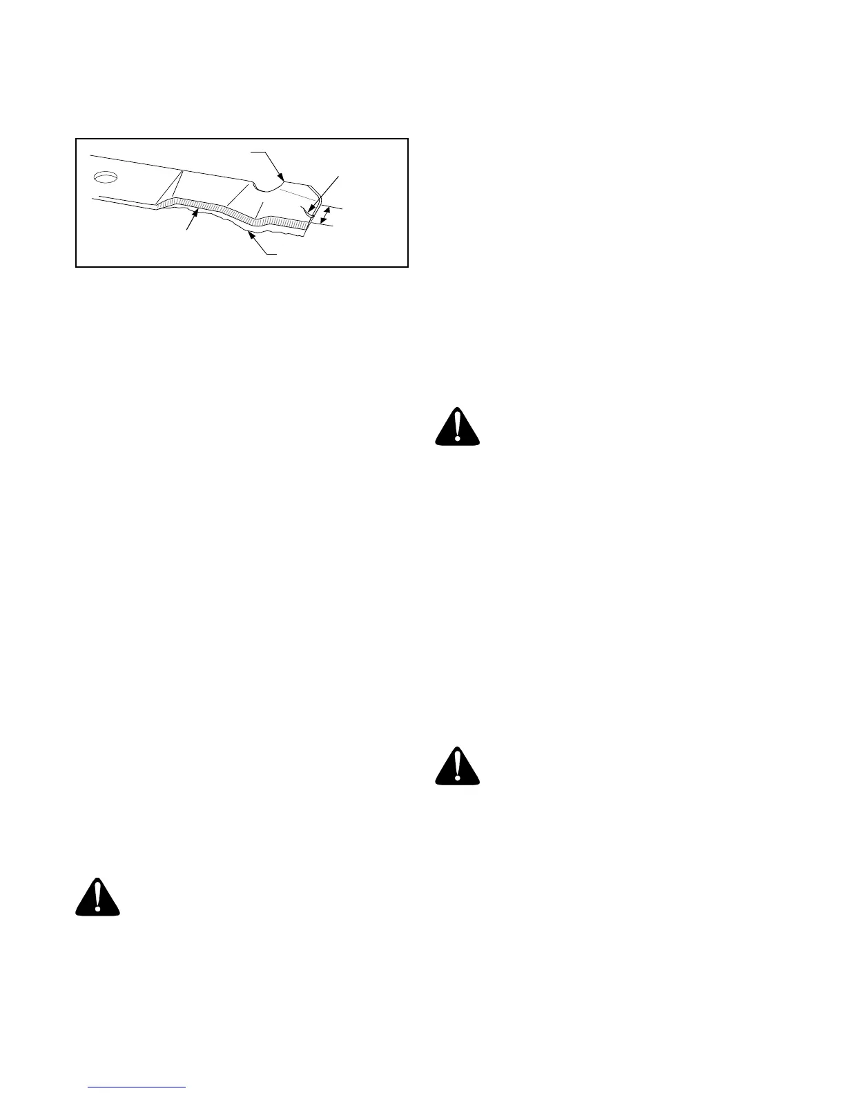
If the cutting edge of the blade has already been
sharpened to within 5/8" of the wind wing radius, or if
any metal separation is present, replace the blades with
new ones. See Figure 25.
Figure 25
It is important that each cutting blade edge be ground
equally to maintain proper blade balance. A poorly bal-
anced blade will cause excessive vibration and may
cause damage to the tractor and result in personal injury.
The blade can be tested by balancing it on a round
shaft screwdriver. Grind metal from the heavy side until
it balances evenly.
IMPORTANT:
When replacing the blade, be sure to
install the blade with the side of the blade marked
‘‘Bottom’’ (or with a part number stamped in it) facing
the ground when the mower is in the operating position.
IMPORTANT:
Use a torque wrench to tighten the blade
spindle hex flange nut to between 70 and 90 ft/lbs.
Battery
The battery is sealed and is maintenance-free. Acid
levels cannot be checked and fluid can not be added.
• Always keep the battery cables and terminals clean
and free of corrosive build-up.
• After cleaning the battery and terminals, apply a
light coat of petroleum jelly or grease to both
terminals.
• Always keep the rubber boot positioned over the
positive terminal to prevent shorting.
IMPORTANT:
If removing the battery for any reason, dis-
connect the NEGATIVE (Black) wire from it’s terminal first,
followed by the POSITIVE (Red) wire. When re-installing
the battery, always connect the POSITIVE (Red) wire its
terminal first, followed by the NEGATIVE (Black) wire. Be
certain that the wires are connected to the correct termi-
nals; reversing them could change the polarity and cause
damage to your engine’s alternating system.
Jump Starting
WARNING:
Never jump start a damaged or
frozen battery. Be certain the vehicles do not
touch, and ignitions are off. Do not allow cable
clamps to touch.
• Connect positive (+) cable to positive post (+) of
your tractor’s discharged battery.
• Connect the other end of the cable to the (positive
+) post of the jumper battery.
• Connect the second cable (negative –) to the other
post of the jumper battery.
• Make the final connection on the engine block of
the stalled tractor, away from the battery. Attach to
a unpainted part to assure a good connection.
IMPORTANT:
If the jumper battery is installed on a
vehicle (i.e. car, truck), do NOT start the vehicle’s
engine when jump starting your tractor.
• Set the tractor’s parking brake and refer to the
instructions on page 13 to start the tractor.
• Disconnect the jumper cables in the reverse order
of connection.
• Allow the tractor’s engine to run for 15 minutes
before shutting it off to allow the alternating system
time to charge the discharged battery.
Charging
If the unit has not been used for an extended period of
time, charge the battery with an automotive type 12-volt
charger for a minimum of one hour at six amps.
WARNING:
Batteries give off an explosive
gas while charging. Charge battery in a well
ventilated area and keep away from an open
flame or pilot light as on a water heater, space
heater, furnace, clothes dryer or other gas
appliances.
Fuse
A fuse is installed in your tractor’s wiring harness to
protect the tractor’s electrical system from damage
caused by excessive amperage.
If the electrical system does not function, or your
tractor’s engine will not crank, first check to be certain
that the fuse has not blown.
It can be found under the hood mounted behind the top
of the dash panel on the support bar. Pull the fuse out
and inspect it to determine if it is good or blown.
IMPORTANT:
Always use a fuse with the same
amperage capacity for replacement.
WARNING:
Before servicing, repairing, or
inspecting, always disengage PTO, set
parking brake, stop engine and remove key to
prevent unintended starting.
Cutting Deck Removal
To remove the cutting deck, proceed as follows:
• Place the PTO knob in the disengaged (OFF)
position and engage the parking brake.
• Lower the deck by moving the deck lift lever into the
bottom notch on the right fender.
• Pull the PTO idler bracket (on deck of Model 1525;
under center of tractor frame Model 1527) against
its tensioner spring to loosen the tension on the
PTO belt and allow the belt to be removed from
around the tractor’s electric PTO clutch. Refer to
Figure 27 or Figure 28.
Blade
Worn Blade Edge
Wind Wing
Sharpen edge evenly
5
/
8
"
m
i
n
i
m
u
m
Separation
 Loading...