Do you have a question about the Cub Cadet 190-302 and is the answer not in the manual?
Refer to Safety Summary and observe all WARNINGS and CAUTIONS when servicing tractors.
Contains specifications for each tractor model in Tables 1-2 through 1-8.
Checklist of recommended procedures for pre-delivery setup of tractors.
Maintenance schedules and lubrication guides found in Section 5.
Section 4 contains troubleshooting and testing info for tractor systems and components.
Instructions to identify and correct problems contained in Section 5.
Manual covers Series 2000 tractors; checks for preparation process and lubrication guides.
Proper battery activation affects its life and performance. Follow steps to avoid premature failure.
Provides basic preventive maintenance and specific lubrication information for Series 2000 tractors.
Guide to ensure all lubrication fittings are installed and functioning correctly.
Overview of troubleshooting and testing for Series 2000 tractor systems and components.
Refer to Table 4-1 for basic description matching the problem experienced.
Provides information on the proper adjustment of various components for Series 2000 tractors.
Explains how corrective maintenance is presented: Removal, Disassembly, Inspection, Repair, Reassembly, Installation.
Procedures for deburring and dressing damaged threads.
Steps for reassembling the hood and grille components.
Steps for installing the hood and grille assembly.
Covers removal, disassembly, inspection, repair, reassembly, and installation of battery and electrical components.
Covers general information, removal, inspection, repair, reassembly, and installation of the PTO clutch.
References Section 4 for electrical troubleshooting of the PTO clutch.
Procedures for deburring and dressing damaged threads.
Steps for reassembling the PTO clutch assembly.
Steps for installing the PTO clutch assembly.
Covers general information, removal, disassembly, inspection, repair, reassembly, and installation of front wheels.
Procedures for repairing minor surface damage or corrosion.
Steps for reassembling the front wheel assembly.
Steps for installing the front rim and assembly.
Covers general information, removal, disassembly, inspection, repair, reassembly, and installation of rear wheels.
Procedures for deburring and dressing damaged threads.
Steps for reassembling the tire and rim assembly.
Steps for installing the steering housing.
Covers general, removal, disassembly, inspection, repair, reassembly, and installation of seat assembly.
Procedures for deburring and dressing damaged threads.
Steps for reassembling the seat switch and seat pan.
Steps for installing compression springs.
Covers general, removal, disassembly, inspection, repair, reassembly, and installation of fender and running board.
Procedures for deburring and dressing damaged threads.
Recommendation for installing seat pivot brackets before fender installation.
Steps for installing the RH and LH seat pivot brackets.
Covers general, removal, disassembly, inspection, repair, reassembly, and installation of dash panel, bulkhead, controls.
Procedures for deburring and dressing damaged threads.
Steps for installing the bulkhead.
Covers general, removal, disassembly, inspection, repair, reassembly, and installation of steering assembly.
Procedures for deburring and dressing damaged threads.
Steps for reassembling the tie rod assembly.
Steps for installing the steering housing.
Covers general, removal, disassembly, inspection, repair, reassembly, and installation of implement lift handle.
Procedures for deburring and dressing damaged threads.
Steps for reassembling the deflector assembly.
Steps for installing mower support pins.
Covers general, removal, disassembly, inspection, repair, reassembly, and installation of fuel tank.
Covers general, removal, disassembly, inspection, repair, reassembly, and installation of control pedals and brake linkage.
Covers general, removal, disassembly, inspection, repair, reassembly, and installation of six speed transmission controls.
Covers general, removal, disassembly, inspection, repair, reassembly, and installation of hydro transmission controls.
Covers general, removal, disassembly, inspection, repair, reassembly, and installation of the drive line.
Covers general, removal, disassembly, inspection, repair, reassembly, and installation of the drive line.
Covers general, removal, disassembly, inspection, repair, reassembly, and installation of clutch assembly, control arm, and linkage.
Covers general, removal, disassembly, inspection, repair, reassembly, and installation of the hydro transmission.
Covers general, removal, disassembly, inspection, repair, reassembly, and installation of hydrostatic transmission.
Covers general, removal, disassembly, inspection, repair, reassembly, and installation of engine and muffler.
Covers general, removal, disassembly, inspection, repair, reassembly, and installation of the frame.
Covers general, removal, disassembly, inspection, repair, reassembly, and installation of the 38-inch mower deck.
Covers general, removal, disassembly, inspection, repair, reassembly, and installation of the 42-inch mower deck.
Covers general, removal, disassembly, inspection, repair, reassembly, and installation of mower deck spindle assembly.
Covers general, removal, disassembly, inspection, repair, reassembly, and installation of the 48-inch mower deck.
Covers general, removal, disassembly, inspection, repair, reassembly, and installation of mower deck spindle assembly.
Procedure for periodically testing and adjusting the braking system.
Covers general information and adjustment of the clutch adjustment rod.
Covers general information and adjustment of the hydro adjustment rod.
Covers general information and adjustment of the shift interlock rod.
Procedure for adjusting the hydro shift stop.
Covers general information and adjustment of neutral for clutch assembly.
Covers general information and adjustment of neutral for hydrostatic transmission.
Covers general information, tractor preparation, and blade assembly preparation for the 42-inch spring trip blade.
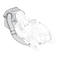
Covers general information, tractor preparation, and snow thrower assembly preparation.
Covers general information and tractor preparation for the 28-inch rear mounted tiller.
| Cylinders | 1 |
|---|---|
| Blades | 2 |
| Cutting Height | 1.5 - 4 inches |
| Cutting Height Positions | 6 |
| Deck Material | Steel |