Connecting the
Hydraulics-
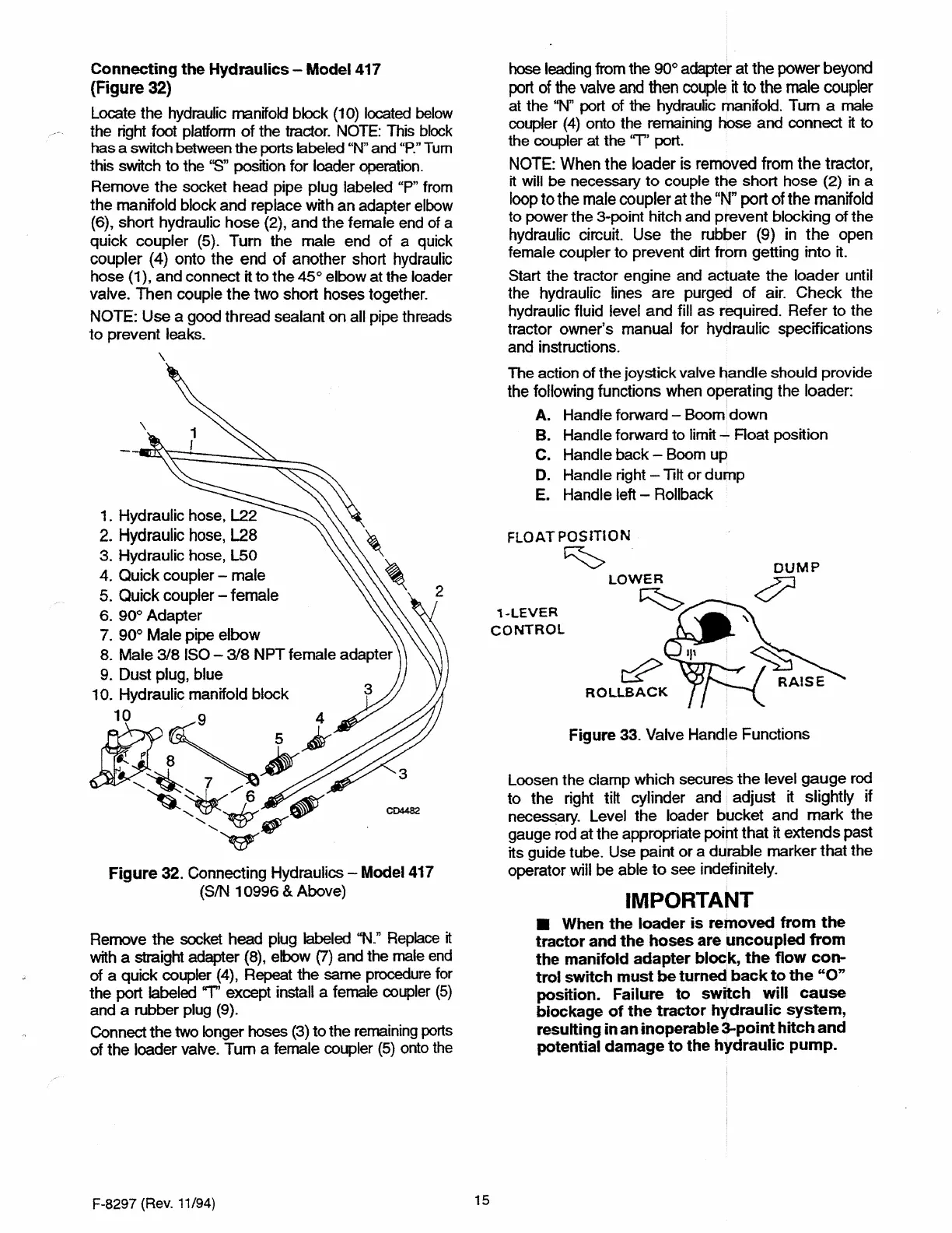
Model 417
(Figure
32)
Locate
the
hydraulic manifold block
(10)
located below
the right foot platform
of
the tractor. NOTE:
This
block
has
a switch between
the
ports labeled "N"
and
"P."
Tum
this switch
to
the
''S"
position
for
loader operation.
Remove
the
socket
head
pipe plug labeled "P" from
the
manifold block
and
replace with
an
adapter elbow
(6), short hydraulic
hose
(2),
and
the
female end of a
quick
coupler
(5).
Turn
the
male
end
of
a quick
coupler
(4)
onto
the
end
of
another
short hydraulic
hose (1),
and
connect it
to
the
45°
elbow at the loader
valve.
Then
couple
the
two
short hoses together.
NOTE: Use a good
thread
sealant
on
all pipe threads
to
prevent
leaks.
\
1. Hydraulic hose, L22
2.
Hydraulic hose,
L28
3. Hydraulic hose,
L50
4.
Quick
coupler -
male
5.
Quick coupler -
female
6.
90°
Adapter
7.
90°
Male
pipe
elbow
8.
Male
3/8
ISO -
3/8
NPT
female adapter
9.
Dust
plug, blue
10.
Hydraulic manifold
block
il/t~~~)r
~:::_,L/5
---~~
1111',
CD4482
V
Figure 32. Connecting Hydraulics - Model 417
(SIN
10996
& Above)
Remove
the
socket head plug labeled
"N."
Replace
tt
with a straight adapter
(8),
elbow
(7)
and the male end
of
a quick coupler (4), Repeat
the
same procedure for
the
port labeled "T' except install a female coupler
(5)
and a rubber plug (9).
Connect
the
two longer hoses
(3)
to
the remaining ports
of
the
loader valve.
Tum
a female coupler
(5)
onto the
F-8297
(Rev.
11/94)
15
hose leading from the
90°
adapter at
the
power
beyond
port of the
valve
and then couple
it
to the
male
coupler
at the
"N"
port
of
the hydraulic manifold.
Tum
a male
coupler
(4)
onto the remaining hose and connect
it
to
the coupler at the
"T''
port.
NOTE:
When
the
loader
is
removed from
the
tractor,
it will
be
necessary
to
couple
the
short
hose
(2) in a
loop
to
the
male coupler at the
"N"
port
of
the
manifold
to power the 3-point hitch and
prevent
blocking
of
the
hydraulic circuit.
Use
the rubber (9)
in
the
open
female coupler
to
prevent dirt
from
getting
into
it.
Start
the
tractor engine and
actuate
the
loader
until
the hydraulic lines
are
purged
of
air.
Check
the
hydraulic fluid level
and
fill
as
required.
Refer
to
the
tractor
owner's
manual for hydraulic specifications
and instructions.
The action
of
the
joystick valve
handle
should provide
the following functions when
operating
the
loader:
A.
Handle forward -
Boom
down
B.
Handle forward to limit -
Roat
position
C. Handle
back
- Boom
up
D. Handle right - Tilt
or
dump
E.
Handle left - Rollback
FLOAT
POSITION
~
1-LEVER
CONTROL
~
ROLLBACK
Figure 33. Valve Handle Functions
Loosen
the
clamp which secures
the
level
gauge
rod
to
the
right tilt cylinder and
adjust
it
slightly
if
nec~ry.
Level
the
loader
bucket
and
mark
the
gauge rod
at
the
appropriate point
that
rt
extends
past
its guide tube. Use paint
or
a
durable
marker
that
the
operator
will
be
able
to
see indefinitely.
IMPORTANT
■ When the loader is removed from the
tractor and the hoses are uncoupled from
the manifold adapter block,
the
flow con-
trol switch must be turned back to the "O"
position. Failure to switch will
cause
blockage of
the
tractor hydraulic system,
resulting in an inoperable 3-point hitch and
potential damage to the hydraulic pump.
 Loading...