Assembling Valve
and
Hoses
- Model 417
(Figure
31)
Open
the
cartons containing
the
valve assembly and
hydraulic components. Remove the end cover
(8)
from
the
valve enclosure
to
gain access and then
remove
the
two 1/4" hex nuts
and
lockwashers from
the
back
side. Attach the valve mounting bracket (7)
and replace
the
hex nuts and lockwashers. There
is
a choice
of
three hole locations in the valve bracket
and
you
must
use
the
hole
at
the
comer.
Insert
the
90°
adjustable elbow
(9)
into the power
beyond port
of
valve and
the
four
straight adapters
( 11) into the work ports. Tighten these fittings
securely. Connect
the
three longer hydraulic hoses
( 1)
to
all three
of
the
inlet
and
outlet ports. Then,
replace_
the
end cover onto
the
valve enclosure.
Fasten
the
valve bracket
to
the
holes located
in
the
rear
of
the
right loader upright using 3/8
NC
x 1"
capscrews, lockwashers and hex nuts. The valve
should
be
located between
the
loader upright and the
tractor, just above
the
loader frame.
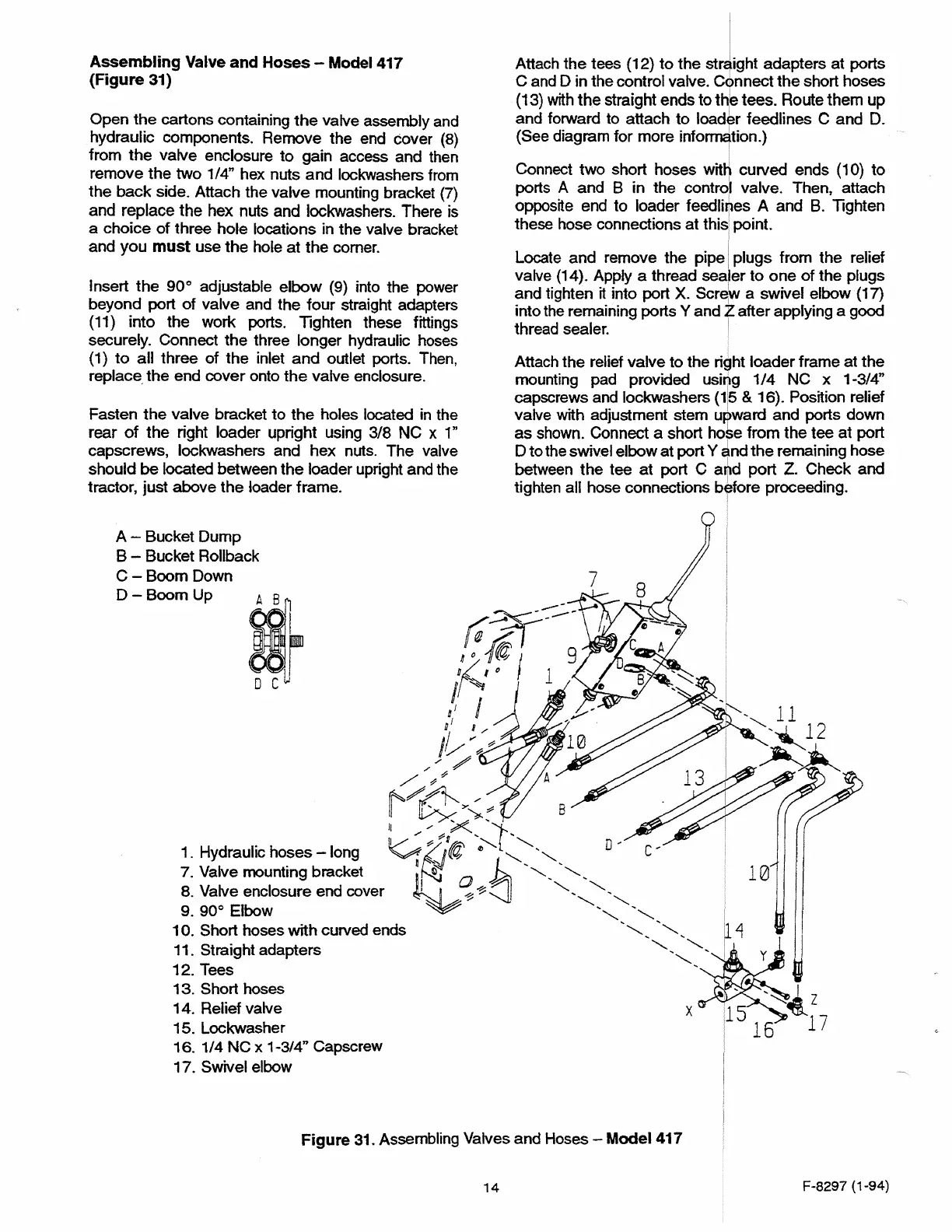
A - Bucket Dump
B - Bucket Rollback
Attach
the
tees
(12}
to
the
stjght
adapters
at
ports
C and D in the control valve.
C<hnnect
the
short hoses
(13)
with
the
straight ends to
th
1
b tees. Route them up
and forward to attach
to
loader feedlines C and
D.
(See diagram for more
info~tion.)
Connect
two
short hoses witij curved ends
(10)
to
ports A and B in the control valve. Then, attach
opposite end to loader feedli~
es
A and
8.
Tighten
these hose connections
at
this
1
point.
Locate
and
remove the pipe
~lugs
from the relief
valve (14). Apply a thread sea
er
to
one
of
the
plugs
and tighten
it
into port
X.
Scr9i a swivel elbow (17)
into the remaining ports Y and Z after applying a good
thread sealer. I
Attach
the
relief valve to the right loader frame at
the
mounting pad provided using
1/4
NC x 1-3/4"
capscrews and lockwashers
(115
&
16).
Position relief
valve
with
adjustment stem upward and ports down
as
shown. Connect a short ho$e from the tee
at
port
D
to
the swivel elbow at port Y
➔
nd
the
remaining hose
between
the
tee
at
port C aljld port
z.
Check and
tighten all hose connections before proceeding.
I
C-BoomDown
D-BoomUp
~-
w
~~_:_-
,''
-#1
9
/~
l
6
1
I
0
1
I,,,
,~
.,~?
,,,✓
/
/
,:;
~/~
/
ll
!L,>x>'~? B
)I
/ X ',--
v
~~
7
96
1fn'i
:,L
...
,,
D ,
1. Hydraulic hoses - long
~
✓
'i'4
~"---
"-,
7.
Valve mounting bracket
~~
0
"-
'----
8. Valve enclosure end cover · I
~~:::JI
...
"-
...
~
"-
...
'----
9. 90° Elbow
...
,
...
,
10. Short hoses
with
curved ends
...
,
......
,
..
11. Straight adapters
"-
..
,
'----
...
12. Tees
--
13.
Short hoses
14. Relief valve
X
15. Lockwasher
16.
1/4
NC
x 1-3/4" Capscrew
17. Swivel elbow
Figure
31. Assembling Valves and Hoses - Model 417
14
10
11
12
z
17
F-8297 (1-94)
 Loading...