Drive Control
WARNING: Run the engine completely dry of
gasoline before tipping snowthrower.
Refer to the Final Adjustment section of the Set-Up instructions
to adjust the drive control. To further check the adjustment,
proceed as follows:
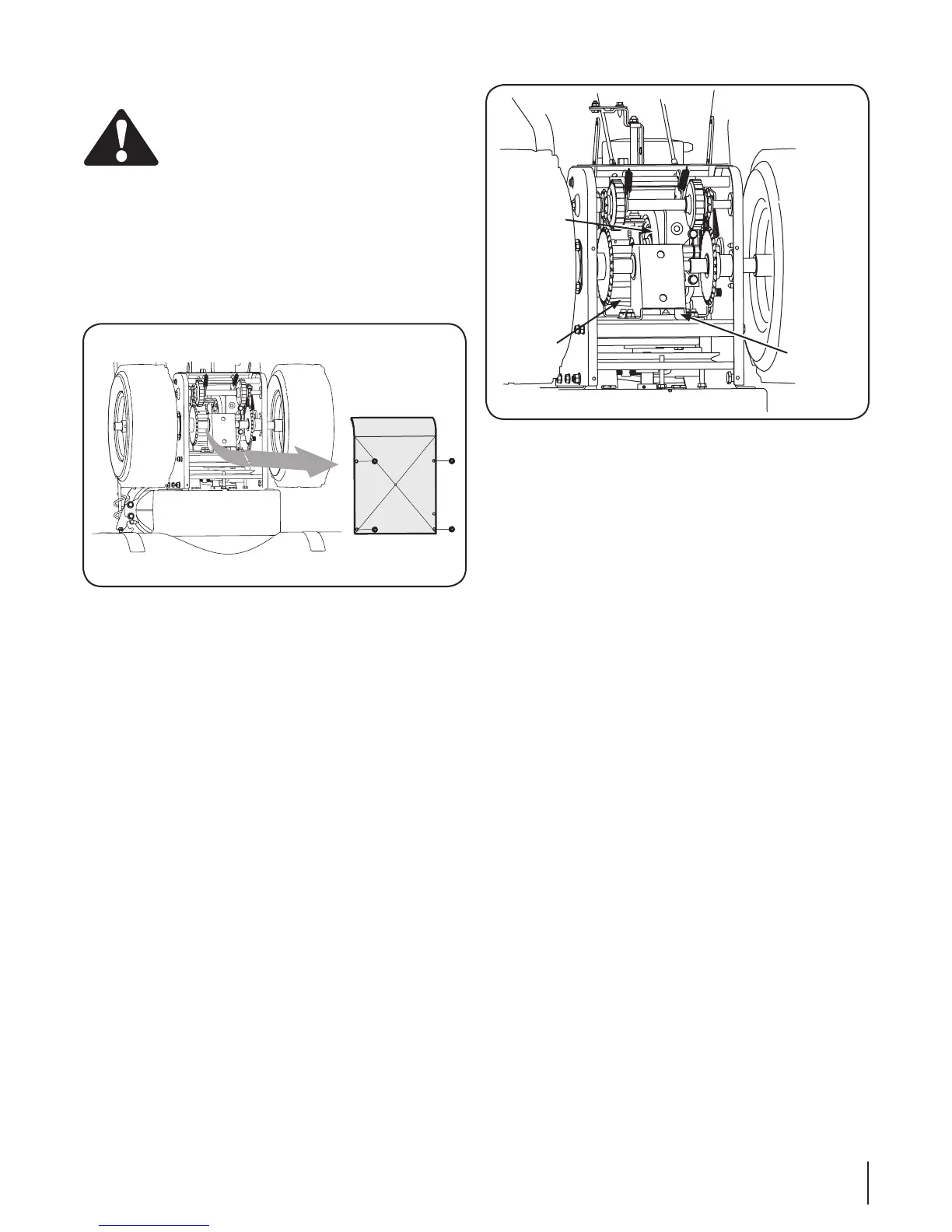
Tip the snow thrower forward, allowing it to rest on the 1.
auger housing.
Remove the frame cover underneath the snow thrower by 2.
removing the self-tapping screws. See Figure 6-6.
With the wheel drive control released, check if there is 3.
clearance between friction wheel and drive plate in all
positions of the shift lever. See Figure 6-7.
With the drive control lever engaged, check if the friction 4.
wheel solidly contacts the drive plate. See Figure 6-7. If not,
adjust as follows:
a. Thread the lock nut outward (down the coupler)
to lengthen the cable and allow the unit to move
freely when the control is released. Refer to Fig.
3-13. Thread the lock nut inward (up the coupler) to
shorten the cable to reduce slippage and prevent
the machine from being easily moved with the drive
control engaged.
5. Reassemble the frame cover.
Auger Control
Refer to the Assembly & Set-up section, “Auger Control Test” for
instructions on adjusting the auger control cable.
Chute Assembly
The remote chute control cables have been pre-adjusted at the
factory. Move the remote chute lever on the control panel back
and forward to adjust angle of the chute assembly.
Skid Shoes
Refer to the Assembly and Set-up section for instructions on
adjusting the skid shoes.
Tire Pressure
Refer to “Assembly & Set-Up” section of this manual.
Off-Season Storage
If the snow thrower will not be used for 30 days or longer, follow
the storage instructions below.
Lubricate the machine as instructed earlier in this section.1.
Store in a clean, dry area.2.
If storing the snow thrower in an unventilated area, 3.
rustproof the machine using a light oil or silicone to coat
the snow thrower.
Clean the exterior of the engine and the snow thrower.4.
NOTE: Refer to the Engine Maintenance section in the separate
engine manual for information on storing your engine.
Figure 6-7
Figure 6-6
Axle
Support
Bracket
Opening
Drive
Plate
Friction
Wheel
17Se c t i o N 6 — Ma i N t e N a N c e & ad j u S t M e N t S
 Loading...