Fig. 3-1
Fig. 3-2
IMPORTANT: The snow thrower is shipped with oil and WITHOUT GASOLINE. After assembly, refer to separate engine manual for
proper fuel and engine oil recommendations.
NOTE: Remove all loose parts and any packing material before assembling.
NOTE: References to right or left side of the snow thrower are determined from behind the unit in the operating position.
NOTE: This Operator’s Manual covers several models, handle
panels, lights and chute cranks are some features that may vary
by model. Not all features referenced (or engines pictured) in
this manual are applicable to all snow thrower models.
NOTE: Replacement auger shear pins are included with this
manual (or stowed in the plastic handle panel). Refer to Augers in
the Maintainance Section for more information regarding shear
pin replacement.
NOTE: For models with electric start the extension cord is
fastened with a cable tie to the rear of the auger housing for
shipping purposes. Cut the cable tie and remove it before
operating the snow thrower.
Assembling Handle
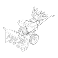
Cut and remove the cable tie holding the chute crank to •
the lower handle.
Look at the lower rear of the snow thrower frame to be sure •
the spring (found at the end of each cable) is attached to
its respective actuator bracket. (Refer to Figures 3-11 and
3-12.)
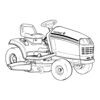
Remove the lower handle knobs, washers and carriage •
bolts (and support tubes if equipped as shown in inset)
from each side of the lower handle. See Figure 3-2.
Raise the upper handle assembly until it locks over the •
lower handle. See Figure 3-1.
Secure the upper handle and lower handle (and support •
tubes if equipped) with the handle knobs, washers and
carriage bolts previously removed.
Tighten the handle knobs already in place on the upper •
holes.
Remove any rubber bands securing the cables to the wing •
nuts.
Assembly & Set-Up
3
7
 Loading...