Loosen but do not remove the locknuts and screws on the •
other two flange keepers.
Loosen but do not remove, the chute bracket in order to •
attach the chute assembly. See Figure 3-5.
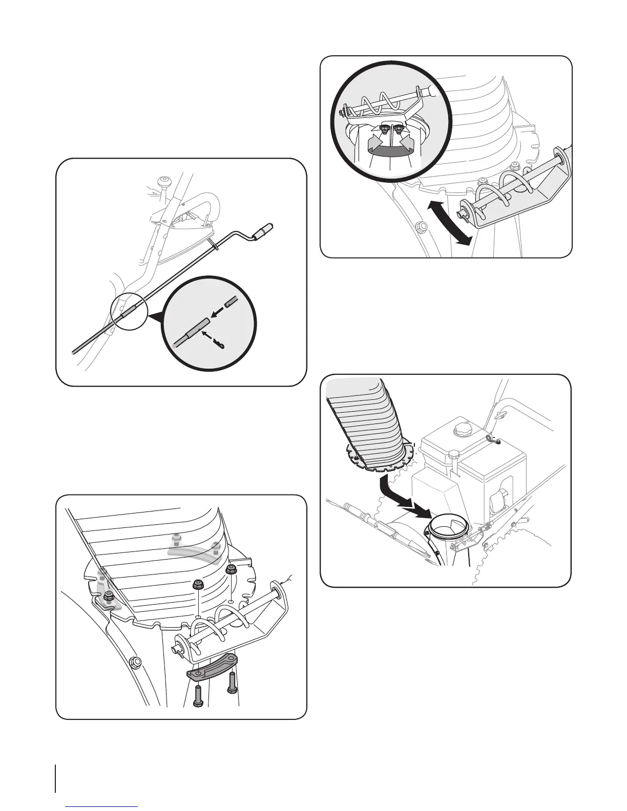
Place the chute assembly onto chute base, making sure the •
flange keepers are beneath lip of chute base. The notches
should engage with the spiral end of the chute crank. See
Figure 3-6.
Retighten the two nuts which secure the chute bracket.•
Secure flange keeper, locknuts and screws previously •
removed. Tighten all flange keepers and hardware with
two 7/16” wrenches. Do not over tighten.
NOTE: If necessary the chute crank support bracket can be
adjusted so the spiral on the chute crank fully engages the teeth
on the chute assembly. Refer to the Adjustment Section.
Fig. 3-6
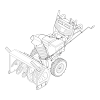
Attaching Chute Crank
Remove the hairpin clip from the upper chute crank and •
slide the upper chute crank into the lower chute crank. A
pair of pliers may help in this job. See Figure 3-3.
Align the two holes on both chute cranks. See Figure a.
3-3.
Secure with the hairpin clip removed earlier.b.
Attaching the Chute Assembly
Cut and remove the cable tie holding the chute assembly •
to the spiral end of the chute crank.
Remove locknuts and screws securing one of the flange •
keepers to the chute assembly. See Figure 3-4.
Fig. 3-5
Fig. 3-4
a
b
Fig. 3-3
8 Se c t i o N 3— aS S e M b l y & Se t -up
 Loading...