Operation(continued)
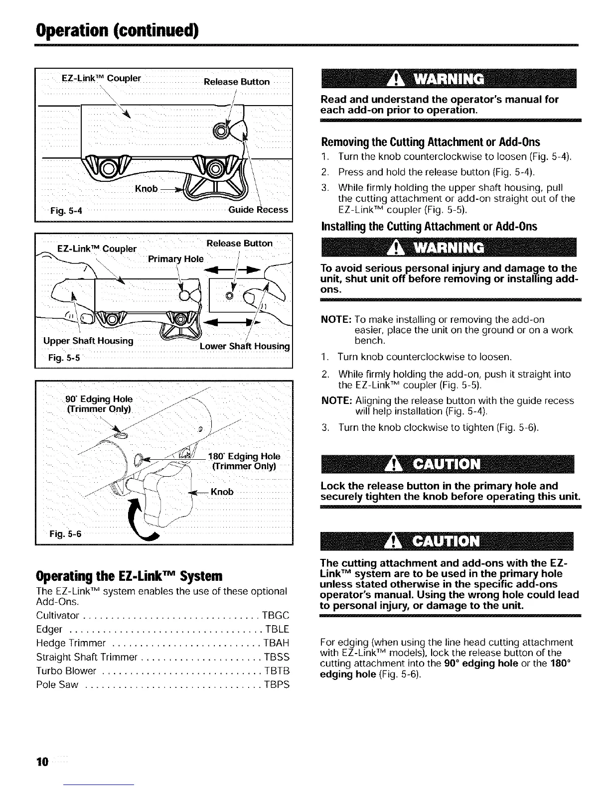
EZ-LinkT M coupler Release Button
Fig. 5-4 Guide Recess
Ez.LinkTMc0uPier Release Button
, /
Upper Shaft Housing ........
Lower _na_ Housm!
Fig. 5-5
90_Edging Hole
(Trimmer Only)
Fig. 5-6 L
180°Edging Hole
(Trimmer Only)
Knob
Operating the EZ-LinkTM System
The EZ-Link TM system enables the use of these optional
Add-Ons.
Cultivator ................................ TBGC
Edger ................................... TBLE
Hedge Trimmer ........................... TBAH
Straight Shaft Trimmer ...................... TBSS
Turbo Blower ............................. TBTB
Pole Saw ................................ TBPS
! ''L
Read and understand the operator's manual for
each add-on prior to operation.
Removingthe Cutting Attachment or Add-0ns
1. Turn the knob counterclockwise to loosen (Fig. 5-4).
2. Press and hold the release button (Fig. 5-4).
3. While firmly holding the upper shaft housing, pull
the cutting attachment or add-on straight out of the
EZ-Link TM coupler (Fig. 5-5).
Installing the Cutting Attachment or Add-0ns
!
To avoid serious personal injury and damage to the
unit, shut unit off before removing or installing add-
ons.
NOTE: To make installing or removing the add-on
easier, place the unit on the ground or on a work
bench.
1. Turn knob counterclockwise to loosen.
2. While firmly holding the add-on, push it straight into
the EZ-Link TM coupler (Fig. 5-5).
NOTE: Aligning the release button with the guide recess
will help installation (Fig. 5-4).
3. Turn the knob clockwise to tighten (Fig. 5-6).
_l!llr! , o
Lock the release button in the primary hole and
securely tighten the knob before operating this unit.
! • ,
The cutting attachment and add-ons with the EZ-
LinkTM system are to be used in the primary hole
unless stated otherwise in the specific add-ons
operator's manual. Using the wrong hole could lead
to personal injury, or damage to the unit.
For edging (when using the line head cutting attachment
with EZ-Link TM models), lock the release button of the
cutting attachment into the 90° edging hole or the 180 °
edging hole (Fig. 5-6).
10
 Loading...