Section 2— ASSembly & Set-Up8
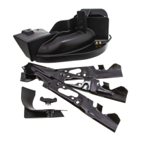
Attach Trip Spring Kit
1. Remove 1 nut (712-04102) from the end
of the trip spring kit (689-00662) and
insert hook end around screw (710-3261)
that was installed previously. Insert
threaded end through mounting hole
in blade and fasten the nut (712-04102)
removed earlier to secure the trip spring
to the blade. See Figure 2-12.
Figure 2-12
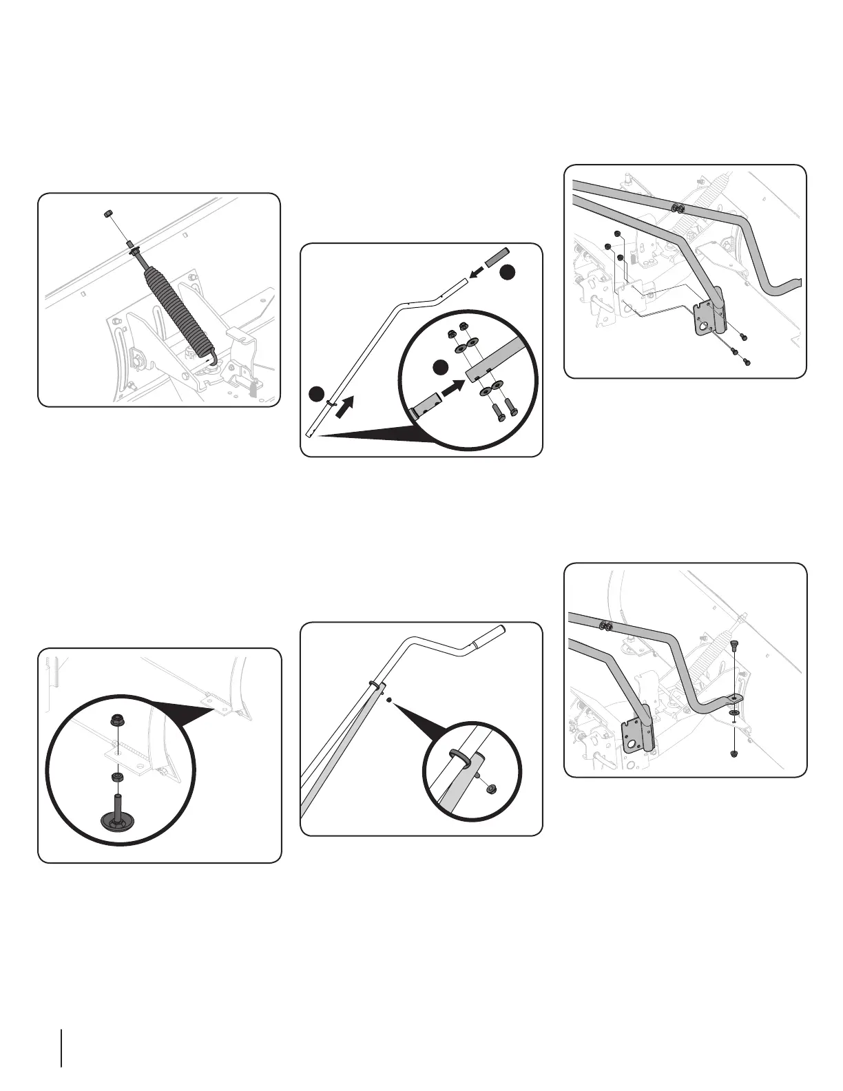
Install Skid Shoes
1. Using the hardware found in hardware
pack 4 (689-00680) thread hex nut (912-
3048) onto skid shoe (703-0650).
2. Slide assembly through the mounting
tab located on the plow blade and use
a flangelock nut (712-04150) found in
hardware pack 4 (689-00680) to secure
the skid shoe assembly to the plow
blade. Hold the skid shoe secure at
the base while turning the top nut to
tighten. See Figure 2-13.
Figure 2-13
3. Repeat steps 1-2 to attach skid shoe
assembly on other side of plow blade.
Note: See the Maintenance &
Adjustments section regarding how to
properly adjust the trip spring and level
out the blade prior to use.
Control Handle Assembly
1. Slide grip (720-0274) onto the end of
the control tube (749-05855) (1). Slide
eye bolt (603-0297) from hardware pack
3 (689-00679) onto control tube (749-
05855)(2). See Figure 2-14.
2. Slide control tube (749-05855) into lower
control tube (749-05858) and fasten with
two bolts (710-3180), 4 curved washers
(736-0451), and 2 flange lock nuts (712-
04063) (3) found in hardware pack 3
(689-00679). See Figure 2-14.
1
2
3
Figure 2-14
3. If not pre-installed from the factory,
install end plug (735-0246A) into end of
lift handle (689-00656).
4. Connect lift handle (689-00656) to
control tube assembly and fasten the
eye bolt (603-0297) with hex flange nut
(712-3004A) found in hardware pack 3
(689-00679). See Figure 2-15.
Figure 2-15
Attach Lift Handle
1. Attach the plate end of the lift handle
(689-00656) to the SHF Assembly
(689-0667) with 3 screws (710-3008),
and 3 flange lock nuts (712-04063) from
hardware pack 3 (689-00679). See Figure
2-16.
Figure 2-16
Attach Control Handle To Pivot
Assembly
1. Attach control tube assembly to pivot
plate assembly (689-00632) with
shoulder screw (738-0143), Teflon
washer (936-0414), and nut (712-04065)
found in hardware pack 3 (689-00679).
See Figure 2-17.
Figure 2-17
 Loading...