Attaching the NegativeBattery Cable
NOTE:The positive battery terminal is marked Pos. (+). The
negative battery terminal is marked Neg. (-).
The positive cable (heavy red wire) is secured to the positive
battery terminal (+) with a hex bolt and hex nut at the factory.
The negative cable (heavy black wire) may be secured to
the negative battery terminal at the factory. If it hasn't been
attached, proceed as follows:
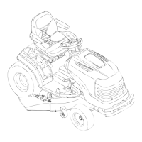
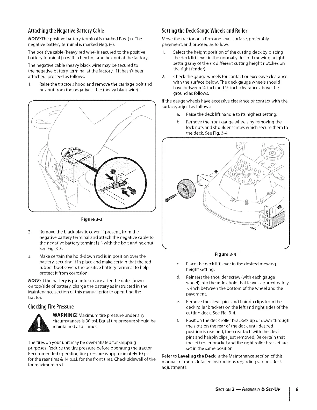
I. Raise the tractor's hood and remove the carriage bolt and
hex nut from the negative cable (heavy black wire).
Figure 3-3
2. Remove the black plastic cover, if present, from the
negative battery terminal and attach the negative cable to
the negative battery terminal (-) with the bolt and hex nut.
See Fig. 3-3.
3. Make certain the hold-down rod is in position over the
battery, securing it in place and make certain that the red
rubber boot covers the positive battery terminal to help
protect it from corrosion.
NOTE: If the battery is put into service after the date shown
on top/side of battery, charge the battery as instructed in the
Maintenance section of this manual prior to operating the
tractor.
CheckingTire Pressure
i_ WARNING! Maximum tire pressure under any
circumstances is 30 psi. Equal tire pressure should be
maintained at all times.
The tires on your unit may be over-inflated for shipping
purposes. Reduce the tire pressure before operating the tractor.
Recommended operating tire pressure is approximately 10 p.s.i.
for the rear tires & 14 p.s.i, for the front tires. Check sidewall of tire
for maximum p.s.i.
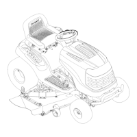
Setting the DeckGaugeWheelsand Roller
Move the tractor on a firm and level surface, preferably
pavement, and proceed as follows
I. Select the height position of the cutting deck by placing
the deck lift lever in the normally desired mowing height
setting (any of the six different cutting height notches on
the right fender).
2. Check the gauge wheels for contact or excessive clearance
with the surface below. The deck gauge wheels should
have between I/4-inch and I/2-inch clearance above the
ground as follows:
If the gauge wheels have excessive clearance or contact with the
surface, adjust as follows:
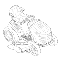
a. Raise the deck lift handle to its highest setting.
b. Remove the front gauge wheels by removing the
lock nuts and shoulder screws which secure them to
the deck. See Fig. 3-4
J
Figure 3-4
c. Place the deck lift lever in the desired mowing
height setting.
d. Reinsert the shoulder screw(with each gauge
wheel) into the index hole that leaves approximately
1/2-inch between the bottom of the wheel and the
pavement.
e. Remove the clevis pins and hairpin clips from the
deck roller brackets on the left and right sides of the
cutting deck. See Fig. 3-4.
fl Position the deck roller brackets up or down through
the slots on the rear of the deck until desired
position is reached, then reattach with the clevis
pins and hairpin clips just removed. Be certain that
the left roller bracket and the right roller bracket are
set in the same position.
Refer to Leveling the Deck in the Maintenance section of this
manual for more detailed instructions regarding various deck
adjustments.
SECTION 2 -- ASSEMBLY& SET-UP 9
 Loading...