32
PRODUCT CARE
WARNING
Do not operate the mower without the wheel weights in place.
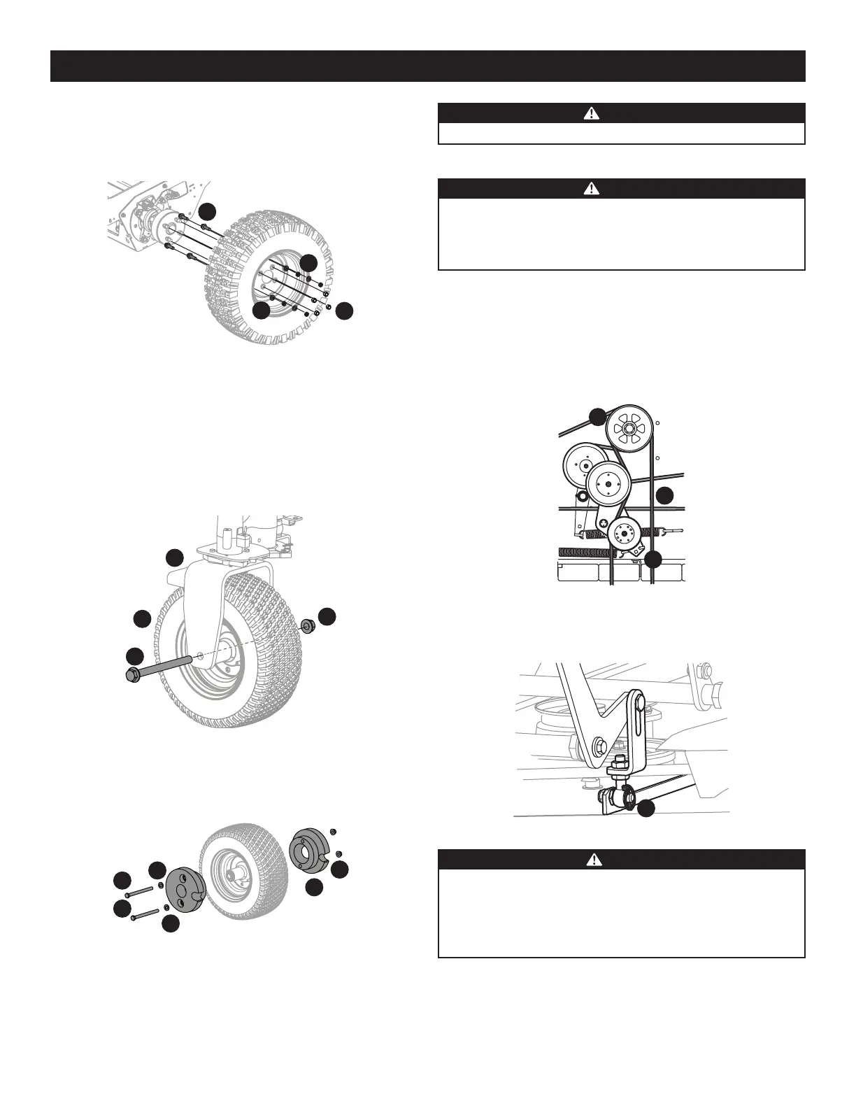
Deck Removal
WARNING
The muffler and any surrounding parts at the rear of the mower may be
extremely hot, and could cause serious burns. Use extreme caution when
near the muffler. Allow the muffler to fully cool before removing the belt
from the PTO pulley.
Remove the mower deck from the mower as follows:
1. Lower the deck to the ground. Capture the deck lift by placing the clevis pin
behind the lowest position.
2. Apply the parking brake. Remove ignition key and the spark plug cap.
3. Using a 1/2” drive in the idler pulley bracket (a), turn the wrench towards the
right of the mower and slide the PTO belt (b) off the PTO pulley (c) (Figure 55).
a
b
c
Figure 55
4. Remove the four lynch pins (a) that secure the deck to the deck lift assembly
(Figure 56).
a
Figure 56
CAUTION
The spring is under tension due to the weight of the deck. When removing
the lift linkage from the deck the tension of the springs will go from the
deck to the deck lift pedal. Not capturing the deck lift pedal by placing the
clevis pin behind the lowest position while removing the lift linkage from
the deck will cause it to snap back.
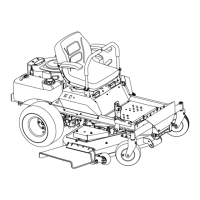
3. Remove the four lug nuts (a) to remove the inner wheel (Figure 52).
4. If replacing the inner tire, remove the four hex screws (b), washers (c) and jam
nuts (d) that hold the mounting screws in place for the dual wheel adapter
(Figure 52).
a
b
c
d
Figure 52
5. Reinstall the tires by reversing the previous steps. Inner wheel lug nuts should
be tightened to 135 ft-lbs (183 N-m), outer wheel lug nuts should be tightened
to 90 ft-lbs (122 N-m) and the jam nuts should be tightened to 42-48 ft-lbs
(57-65 N-m).
Front Tire Removal/Replacement
1. Remove the hex screw (a) and flange lock nut (b) that secures the front wheel (c)
to the yoke assembly (d) (Figure 53).
c
d
b
a
Figure 53
2. Remove the two 25-lb weights (a) on each tire by removing the two hex screws
(b), flat washers (c) and flange lock nuts (d) that secure them to the rims
(Figure 54).
a
b
b
c
c
d
Figure 54
3. To re-install or replace the front tire, reverse Steps 1 and 2. Tighten the hardware
in Step 2 to 65-75 ft-lbs (88-102 N-m) and the hardware in Step 1 to 75-90 ft-lbs
(101-122 N-m).

 Loading...