35
PRODUCT CARE
TROUBLESHOOTING
WARNING
Before cleaning, repairing, or inspecting, make certain the blade(s) and all moving parts have stopped. Turn off the engine, remove the key, disconnect the
spark plug wire(s) and the negative battery cable to prevent unintended starting. Always wear safety glasses or safety goggles during operation and while
performing an adjustment or repair to protect your eyes.
This section addresses minor service issues.
Problem Cause Remedy
Excessive vibration 1. Cutting blade loose or unbalanced.
2. Damaged or bent cutting blade.
1. Tighten blade and spindle.
2. Replace blade.
Uneven cut 1. Deck not properly leveled.
2. Cutting blade dull or damaged.
3. Uneven tire pressure.
1. Perform side-to-side deck adjustment.
2. Sharpen or replace cutting blade.
3. Check and correct tire pressure in all four tires.
Mower will not mulch grass 1. Engine speed too low.
2. Wet grass.
3. Excessively high grass.
4. Dull blade.
1. Place throttle in FAST (rabbit) position.
2. Do not mulch when grass is wet.
3. Mow once at a high cutting height, then mow again at
desired height or make a narrower cutting swath.
4. Sharpen or replace blade.
Engine fails to start 1. PTO/blade engaged.
2. Blown fuse.
3. Parking brake not engaged.
4. Pedal sensor engaged (Hydro-Gear S transmission models only).
1. Place blade engage lever in disengaged (OFF) position.
2. Replace fuse(s).
3. Engage parking brake.
4. See authorized dealer.
See Engine Operator’s Manual.
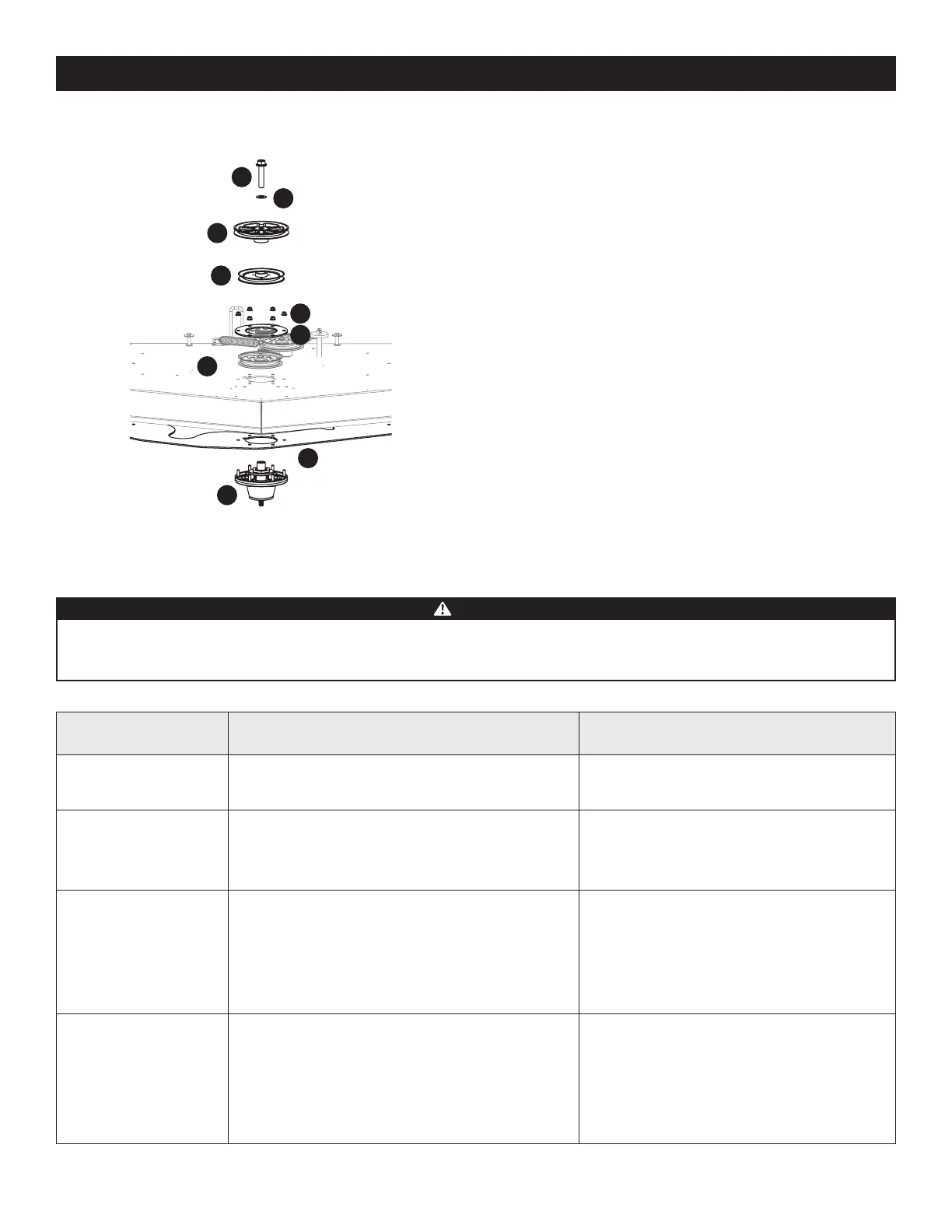
8. Remove the hex flange bolt (a) and flat washer (b) securing the drive pulley (c)
and center spindle pulley (d) to the spindle assembly (e) (Figure 66).
a
b
c
d
e
f
g
h
i
Figure 66
9. Remove the 6 flange lock nuts (f) securing the center spindle pulley (d), spindle
assembly (e) and the support plates (g) to the deck shell (h) (Figure 66).
NOTE: The deck support plate (i) does not need to be removed unless all three
spindles are being replaced (Figure 66).
10. Reverse the process to install the spindle assembly. When installing the new
spindle assembly be sure to install the hardware exactly (Figure 65 on page 34
and Figure 66). Torque the hex flange bolts to 250 ft-lbs (339 N-m) and the flange
lock nuts to 21-32 ft-lbs (28-43 N-m).
Changing the Transmission Drive Belt
Several components must be removed and special tools used in order to change
the mower’s transmission drive belt. See your authorized service dealer to have the
transmission drive belt replaced.
Mower Creeping
Creeping is the slight forward or backward movement of the mower when the
throttle is on and the speed control pedals are in the neutral position. If your mower
creeps, see your authorized service dealer.

 Loading...