14 Section 3 — controlS & operation
2. Move the ROPS into the desired position. The
three positions are TRANSPORT (a) position,
TRANSPORT WITH BAGGER (b) position and
into the OPERATION (c) position. See Figure 3-2.
3. Rotate both locking pins into the LOCKED
position. Move the upper ROPS slightly until
the locking pins are fully engaged in the
LOCKED position.
Accessory Switch Receptacles
The two receptacles (SD models) or one receptacle
(SDL models) for optional accessories are on the
RH console. See the Attachments & Accessories
section for information. The receptacle(s) are for
switches for an optional electric deck lift, lights
and/or an auxiliary switch.
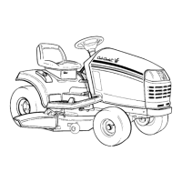
Work and Beacon Lights
Located in front of the two accessory switch
receptacles on the RH console, this three-way
switch toggles between:
• Lights OFF (center position)
• Beacon Light ON (right position)
• Beacon Light and Work Lights ON (left
position. See Figure 3-4.
LIGHTS
+
Work Lights
Beacon Light
Figure 3-4
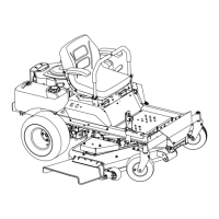
Setting the Beacon Light
The Beacon Light should be positioned upright
at all times while operating the tractor. To set the
beacon light:
1. Set the ROPS to the desired position as
previously instructed.
2. Loosen the knob at the base of the beacon
light assembly and slide the assembly out of
the groove securing it in position.
3. Rotate the assembly to face the beacon light
straight upward. See Figure 3-5.
Figure 3-5
4. Slide the pertinent groove on the beacon
light assembly securely into place with the
knob, and tighten the knob.
Note: In Figure 3-5 the ROPS is shown in
Transport Position. Take note of the settings
used for the different beacon light positions.
See Figure 3-6.
Operation Position
Transport Position
Transport With Bagger
Position
Figure 3-6
12V Outlet (If Equipped)
The 12V outlet is located to the right of the
operator’s seat on the lower panel of he RH console
and is used for the convenience of plugging in
accessories that require a power source with a
maximum load of 5A at 12V.
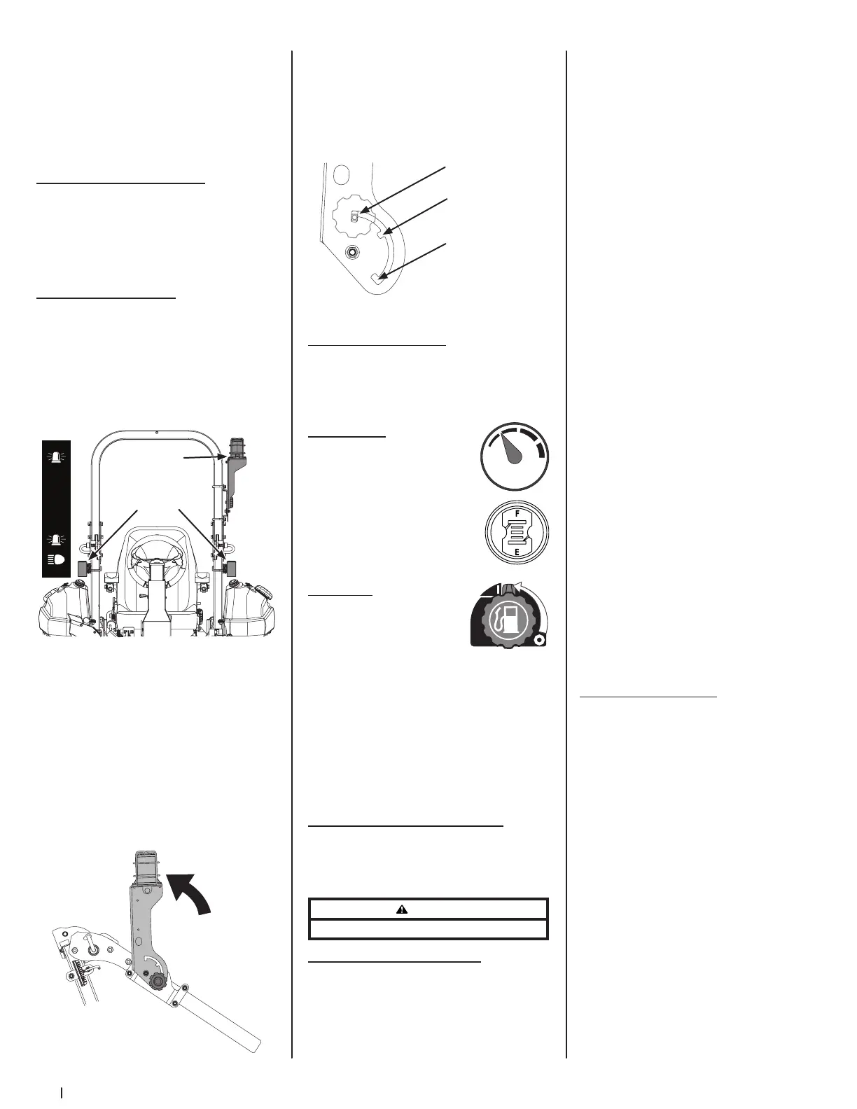
Fuel Gauge(s)
There is a fuel gauge on top of each
of the two fuel tanks or a single
gauge to the right of the operator’s
seat on the RH console. The gauges
measure the fuel level in each tank.
Fuel Valves
The fuel valves are located near
the rear of each fuel tank. The
valve controls the fuel flow from
the right and left tank and also
can shut off fuel flow to the engine. Rotate the
valve counterclockwise to open the flow from the
tank(s). Rotate the valve clockwise to stop the flow
from the tank(s). The fuel tanks can be operated
together, independently or shut the fuel flow off
completely.
Note: IF both tanks are on, and one is empty the
engine will not start. Be certain to make sure both
tanks have fuel or that the empty tank’s fuel valve
is closed.
Front Wheel Weights (Not Shown)
There are four 25-lb tire weights on the front of the
tractor for a total of 100-lbs. Two 25-lb weights on
each tire, one on the inside and one on the outside
of the front rims.
WARNING
Do not operate the tractor without the wheel weights in place.
Before Operating Your Tractor
1. Before you operate the tractor, study this
manual carefully to familiarize yourself with the
operation of all the instruments and controls.
It has been prepared to help you operate and
maintain your machine efficiently.
2. Fill the fuel tank with only clean, fresh,
unleaded gasoline with a pump sticker
octane rating of 87 or higher. When the
fuel reaches ⁄” below the bottom of the fill
neck, stop. DO NOT OVERFILL. Space must
be left for expansion.
3. Never use gasoline containing more than
10% ethanol or methanol.
4. Check the engine oil level as instructed in
the Engine Operator’s manual.
5. Check the transmission oil level. The
transmission oil expansion reservoir is
located beneath the operator’s seat. Always
wipe off the area around the reservoir fill
neck before checking the oil level to prevent
dirt from contaminating the oil. Remove the
cap and make sure the oil level is a ¼” above
the bottom of the reservoir. If the oil level is
low, fill with Castrol™ (Syntec®) Edge™.
6. Check the tire inflation pressures 10-12 psi
for the rear tires, 20-25 psi for the front tires.
Note: New tires are over-inflated in order to
properly seat the bead to the rim.
7. Check that all nuts, bolts and screws are tight.
8. Check the tension of the deck drive belts.
a. Remove the deck cover
b. The tension of the deck drive
belts are maintained by a spring
mechanism that adjusts for wear and
stretch.
c. Examine the belts for cuts, fraying,
and excessive wear. Replace if any of
these are detected.
d. Replace the deck cover.
9. Check if deck is level. When correctly
adjusted the mower deck should be level
side to side, and the front of the deck should
be approximately ⁄” lower than the rear of
deck. If deck needs to be leveled, refer to
the Service section.
10. Lubricate all pivot points listed in the
Service section.
11. Adjust the seat for operator’s maximum
comfort, visibility and for maintaining
complete control of the machine. Refer
to the Assembly & Set-Up section for
instructions on adjusting the seat.
Safety Interlock System
This machine is equipped with a safety interlock
system for the protection of the operator. If the
interlock system should ever malfunction, do not
operate the machine. Contact your authorized
service dealer.
• The safety interlock system prevents the
engine from cranking or starting unless
the speed control pedals are in the neutral
position, the parking brake is engaged, and
the PTO knob is disengaged.
• To avoid sudden movement when
disengaging the parking brake, the safety
interlock system will shut off the engine if the
speed control pedals are moved to a position
other than the neutral position when the
parking brake is engaged.
• The safety interlock system will shut off the
engine if the operator leaves the seat before
engaging the parking brake.
• The safety interlock system will shut off
the engine if the operator leaves the seat
with the PTO knob engaged, regardless of
whether the parking brake is engaged.
Note: The PTO knob must be in the
disengaged position to restart the engine.
 Loading...