CONTENTS
Section
Page
I
II
III
IV
V
Emission Control Systems Warranty ... 2
Tractor and Deck Preparation .............. 3
Safe Operation Practices ..................... 4
Product Graphics ................................. 7
To The Owner ...................................... 8
Calling Service Information .................. 8
Recording Model & Serial Number ...... 8
Controls and Indicators ........................ 9
Operation ............................................. 14
Adjustments ......................................... 18
Maintenance ........................................ 23
Mower Deck ......................................... 33
Section
Vl
VII
Page
Off-Season Storage ............................. 45
Mowing ................................................. 46
Optional Equipment and Accessories. 47
Maintenance Chart ............................... 48
Trouble Shooting .................................. 49
Lubrication Table ................................. 51
Lubrication Guide ................................. 52
Slope Gauge ........................................ 55
Specifications ....................................... 57
Warranty -- Commercial Use ............. 58
Warranty -- Residential Use ............... 59
Maintenance Parts Chart .................... 60
TRACTOR AND DECK PREPARATION
1. ATTACHING THE CHUTE DEFLECTOR
For shipping purposes, the mulching plug has been in-
stalled in the mower deck. The mulching plug must be
removed to install the chute deflector assembly.
1.
, WARNING
Do not operate the mower deck, even with the
mulching plug installed, unless the chute
defelector has been properly installed.
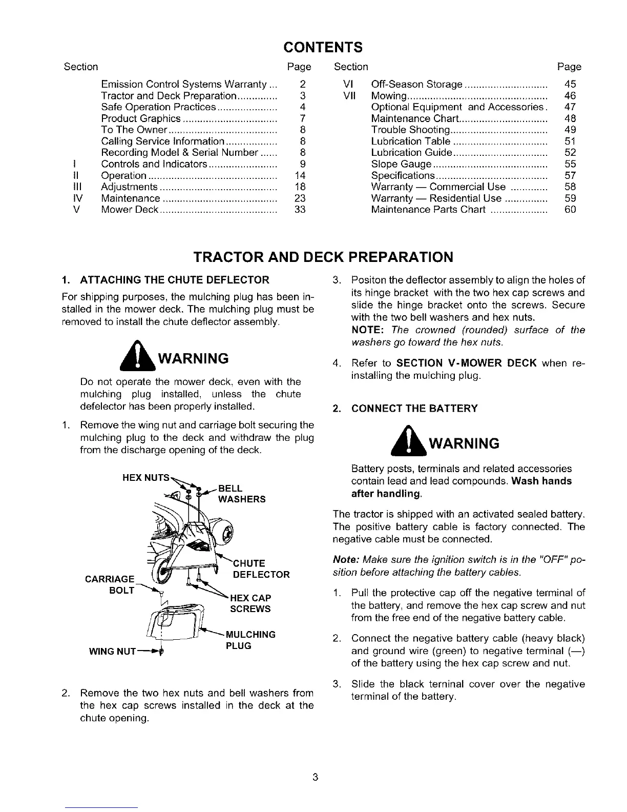
Remove the wing nut and carriage bolt securing the
mulching plug to the deck and withdraw the plug
from the discharge opening of the deck.
"_ WASHERS
CARRIAGE DEFLECTOR
BOLT _. 4 HEX CAP
_ SCREWS
MULCHING
WING NUT -_'!_ PLUG
2. Remove the two hex nuts and bell washers from
the hex cap screws installed in the deck at the
chute opening.
3.
4.
Positon the deflector assembly to align the holes of
its hinge bracket with the two hex cap screws and
slide the hinge bracket onto the screws. Secure
with the two bell washers and hex nuts.
NOTE: The crowned (rounded) surface of the
washers go toward the hex nuts.
Refer to SECTION V-MOWER DECK when re-
installing the mulching plug.
2. CONNECT THE BATTERY
, WARNING
Battery posts, terminals and related accessories
contain lead and lead compounds. Wash hands
after handling.
The tractor is shipped with an activated sealed battery.
The positive battery cable is factory connected. The
negative cable must be connected.
Note: Make sure the ignition switch is in the "OFF" po-
sition before attaching the battery cables.
1.
2.
3.
Pull the protective cap off the negative terminal of
the battery, and remove the hex cap screw and nut
from the free end of the negative battery cable.
Connect the negative battery cable (heavy black)
and ground wire (green) to negative terminal (--)
of the battery using the hex cap screw and nut.
Slide the black teminal cover over the negative
terminal of the battery.
3

 Loading...