15Section 2 — ASSembly & Set-Up
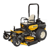
4. Insert the wiring harness into the bottom of the seat as
shown in Figure 3-12.
Figure 3-12
NOTE: When the harness is connected, be sure to push the
excess wire from the wire harness into the seat box hole
before continuing.
Seat Adjustment
This tractor is equipped with an adjustable seat, which includes a
retractable seat belt assembly and an Operator Presence Sensor
(OPS). The OPS in the form of a switch, is integrated into the seat
bottom and is connected to the machine electrical system.
The seat can be adjusted forward and back and the arm rest can
be adjusted up and down.
To move the seat forward or back, locate the seat adjustment rod
under the seat. Push the rod to the left and slide the seat forward
or back into the desired position and release the rod when the
seat is in the desired position. See Figure 3-13.
Figure 3-13
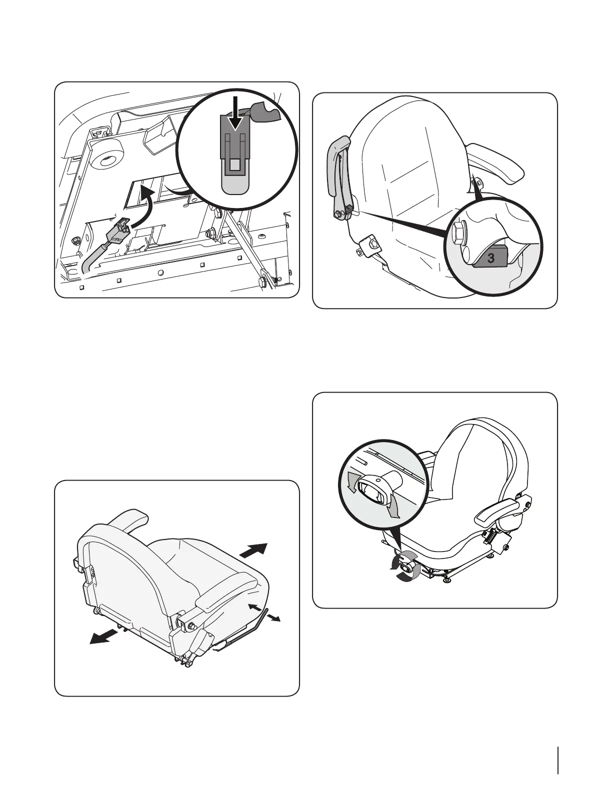
To adjust the arm rest, lift the arm rest and rotate the block
adjustment into one of the four positions (0-3, 0 being the lowest
and 3 being the highest.) and lower the arm rest. See Figure 3-14.
Figure 3-14
The mechanical suspension mechanism (if equipped)
incorporates weight/ride adjustment controls for operators in
the 125 to 275 lb. weight range (turn the knob on the front of
the seat clockwise to increase the weight capacity and counter-
clockwise to decrease. See Figure 3-15.
Figure 3-15
NOTE: The seat base must be secured by the latch,
otherwise, the seat assembly could tilt forward. The
Operator Presence Sensor must be connected to the
electrical wiring harness.

 Loading...