12 se c t i O n 2— as s e M b l y & se t -up
Adjusting Drive Control Levers
control lever and seat adjustment will result in the following:
In the neutral position with hands on the control levers,
approximately vertical.
In the full forward position,
In the full reverse position,
torso.
Adjustment lever is located under the front edge of the
seat.
The seat has five inches of front-to-rear adjustment
available.
Check factory settings of control levers for the conditions listed
above.
NOTE: If control lever adjustments are required, height
adjustments should be made prior to angular adjustments.
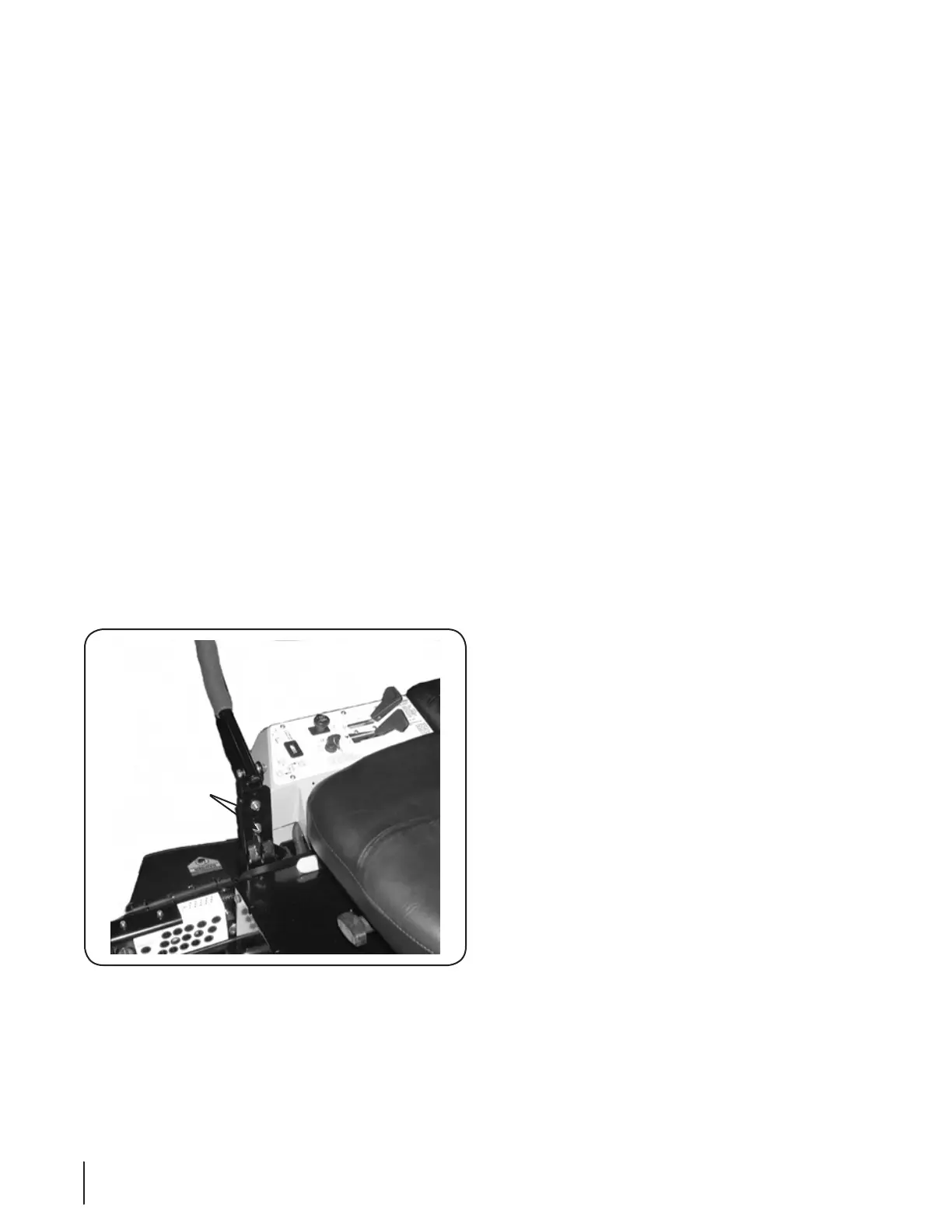
To adjust the height of the drive control levers:
Remove the nuts from the control lever mounting bolts.
Remove the bolts and control lever and reposition to the 2.
second set of holes in the mounting block.
If angular adjustments are also required, nuts can be 4.
tightened until snug at this point.
The same adjustments should be made to both sides of the
mower.
To adjust the front-to-rear angle of the control levers:
Loosen the nuts on the control lever mounting bolts,
leaving the bottom one fairly snug. The top hole is slotted,
allowing the control lever to pivot on the bottom bolt.
Move control lever to the desired angle and tighten the 2.
NOTE: In the neutral position, the handles of the control
levers should be aligned with approximately a one inch
gap between the tips. Widen the gap by adding shim
washers to the top mounting bolt between the lap bar and
the mounting block.
Check the results of any adjustments to the conditions
described above. Repeat any adjustment procedures as
required until all conditions are met.
Suspension Seat
This unit is equipped with an adjustable suspension seat
system, which includes a fold-forward seat with retractable
seat belt assembly, a low profile mechanical suspension,
The seat bottom is covered with a heavy-duty vinyl 2.
fabric and integrates the EVC cushion comfort system
⁄” dampered (for shock isolation)
integrated into the seat bottom and is connected to the
machine electrical system. The seat back is also covered
degrees, and it will fold forward for transport or protection
left side). The armrests are adjustable for operator comfort
(knob inside armrests actuated from the bottom). Roller
bearing single-locking tracks provide easy repositioning
fore/aft up to 5” (lever actuated on lower right).
A mechanical suspension mechanism incorporates weight/
lb. weight range (turn the knob on the front of the seat
clockwise to increase the weight capacity and counter-
throughout the suspension mechanism that provides an
additional 2” of suspension travel.
A retractable seat belt assembly with inertia-lock is 4.
attached to the “ride” portion of the seat frame. The seat
frame is attached to the mechanical suspension, which is
attached to the roller tracks that are bolted to the seat base
factory installed position.
When the seat latch is released, the complete seat 5.
assembly and seat base can be pivoted forward onto the
foot platform - this provides access to the battery, hydraulic
reservoir and filter, as well as some of the electrical system
and control linkages. The seat base must be secured with
the latch prior to machine operation.
NOTE: The seat base must be secured by the latch, otherwise, the
must be connected to the electrical wiring harness.
Drive Control
Lever Mounting
Bolts & Nuts
Figure 3-7
 Loading...