Z Force
17
• Terminal A: Yellow wire with black trace from
relay #1, terminal E. When relay #2 is ener-
gized, Terminal A has contact with Terminal E.
Terminal A has contact with terminal C when
relay #2 is not energized.
• Terminal B: 2 black wires. Power is provided to
the windings through the seat switch, when the
seat is unoccupied. Second black wire is a
jumper to terminal B on relay #3.
• Terminal C: 2 green wires. One is a jumper to
terminal D on relay #2. The second one is a
ground path through the G terminal on the key
switch. When relay #1 is not energized (parking
brake off) and relay #2 is energized (seat
vacant), a ground path is provided for the mag-
neto, turning off the engine.
• Terminal D: 2 green wires. One is a jumper from
terminal C, the other is a ground path. The G
terminal on the key switch finds it’s ground
through the jumper wire.
• Terminal E: Empty.
10.13.Relay #3: See Figure 10.13.
• Terminal A: Yellow wire with black trace, from
terminal B on the PTO switch. Terminal A has
continuity with terminal C when relay #3 is ener-
gized by the absence of a butt in the seat. When
the PTO switch is on, and the seat is empty, the
magneto is grounded, turning off the engine.
• Terminal B: Black jumper wire from Terminal B
on relay #2. Provides power to the windings of
both relays when the seat is occupied.
• Terminal C: 2 Green wires. One is a jumper wire
to Terminal D. The second green wire leads to
the neutral switches, providing a ground path for
them through jumper to terminal D.
• Terminal D: Two green wires. One is a jumper to
terminal C. The other is a constant ground for
the relay #3 windings and terminal C.
• Terminal E: Empty.
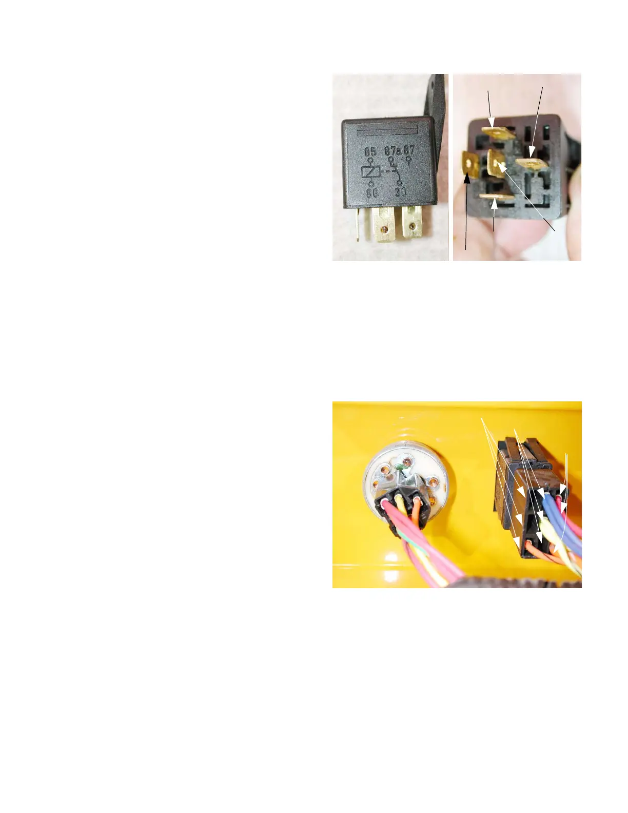
10.14.The key switch is located in the right side control
console. The terminal locations are clearly
marked on the back of the switch. The switch
f u n c t i o n s a s f o l l o w s : S e e F i g u r e 1 0 . 1 4 .
• Off: terminals G, M, and R, have continuity.
• Run: terminals B,R, and L, have continuity.
• Start: terminals B, S, and L, have continuity.
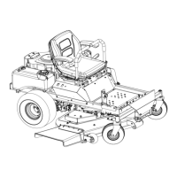
Figure 10.13
30 = A
86 = B
87A = E
85 = D
87 = C
Figure 10.14
N.C. terminals
N.O. terminals
Common
terminal
www.mymowerparts.com
K&T Saw Shop 606-678-9623 or 606-561-4983

 Loading...