Z Force
22
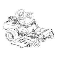
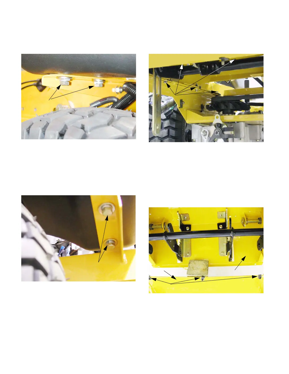
11.20. Loosen the bolts that hold the back of the gas
tank to the frame at least three turns using a
9/16” wrench. See Figure 11.20.
11.21. Loosen the bolts that hold the back of the utility
bin to the frame at least three turns using a
9/16” wrench.
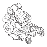
11.22. Remove the bolts that hold the front of the fuel
tank and the utility bin to the front tank mounting
bracket using a 9/16” wrench. See Figure 11.22.
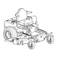
11.23. Remove the bolts that hold the control housing
to the frame using a 3/8” socket.
See Figure 11.23.
NOTE: There are three bolts along the front
edge that come down from the top. Two bolts are
accessible from the bottom on each side. Two
bolts are accessible from above on the rear cor-
ners of the control housing.
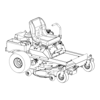
11.24. Lift the front of the control housing and support it
with a 4 X 4 or similar dimensional lumber.
See Figure 11.24.
11.25. Push the lift shaft assembly up into the top of the
control housing, allowing the arms to hang
straight down.
NOTE: Do not cock the lift shaft assembly when
manipulating it, or it will get stuck.
Figure 11.20
Rear fuel tank mounting bolts
Figure 11.22
Front fuel tank mounting bolts
Figure 11.23
Control housing bolts
Figure 11.24
Frame
Control housing
J-nuts
www.mymowerparts.com
K&T Saw Shop 606-678-9623 or 606-561-4983

 Loading...