Wiring Diagram
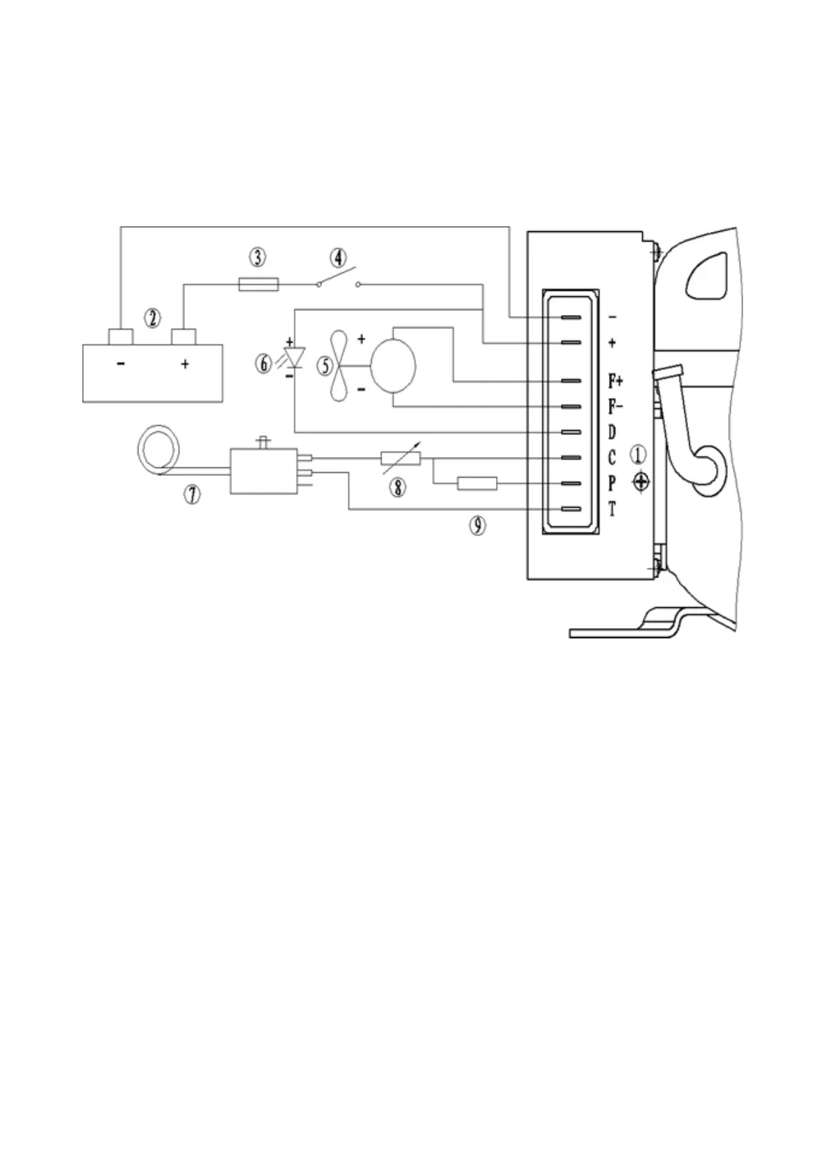
The electronic driver features a terminal board where all connections are made. The terminal lay out is
described in Figure 1:
External Fan
Fig. 1. Wiring scheme
As shown in Figure 1. (5), the positive side of the fan is connected to the (F +) end of the controller, and the
negative terminal of the controller is connected to the (F-) terminal of the controller. A terminal of the
controller (F +) and (F-) can be connected with a 12V DC fan The When the input voltage of the controller
exceeds 12V, the output value between the terminals (F +) and (F-) is always kept at 12V.
Regardless of whether the input voltage system is 12V or 24V, the fan must be a 12V DC fan. B, the
controller can continue to output 0.5A fan drive capability.