Wiring Diagrams
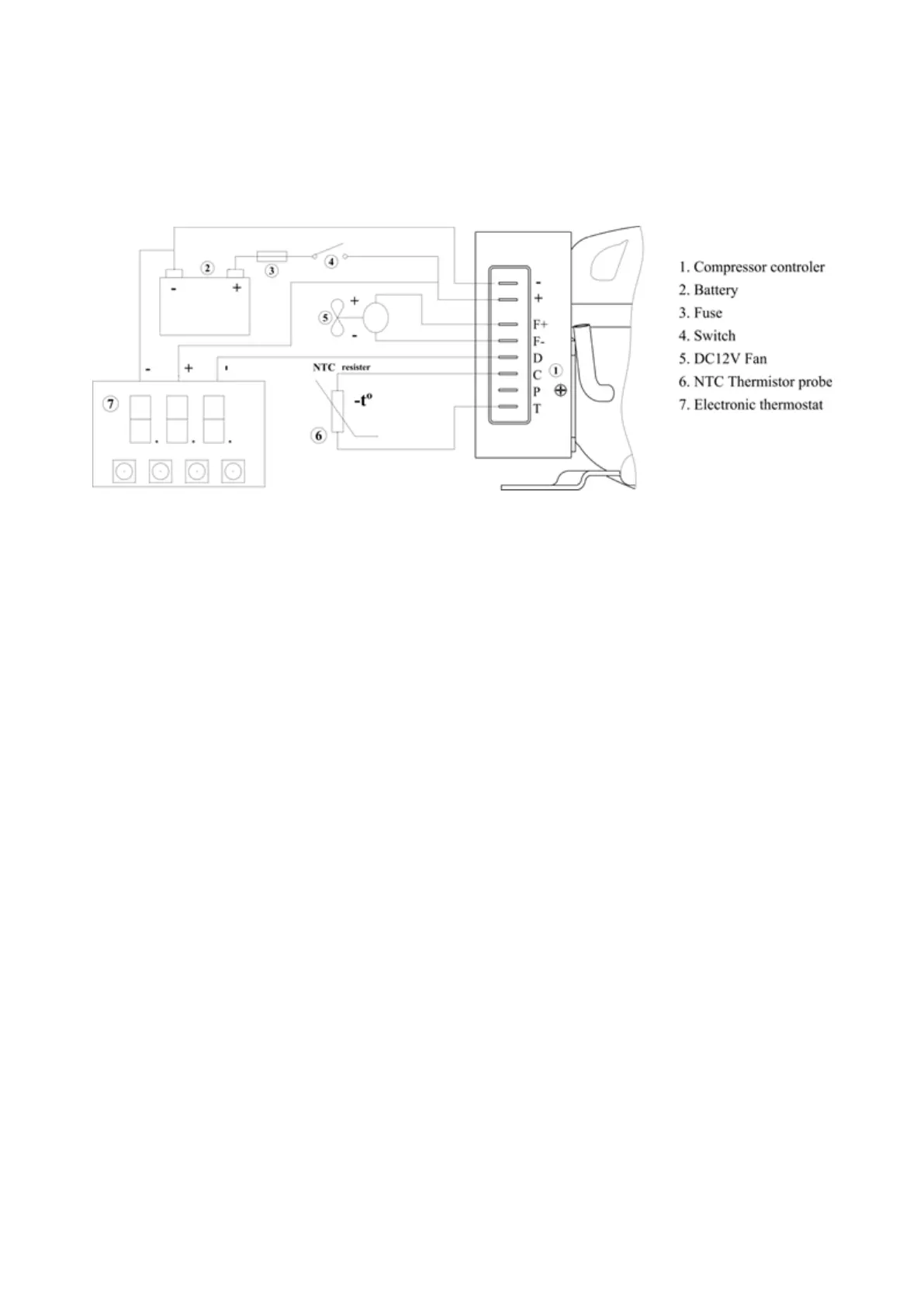
The electronic driver features a terminal board where all connections are made. The terminal layout is
described in Figure 2:
1. +/- pins are the DC input of 6.3: connect the negative pole and the positive pole respectively
2. F+, F- pins are the Fan output of 6.3: connect to fan of DC 12V
3. D pin is the data communication interface, transmitting the data between the thermostat and the
compressor controller
4. C pin is the control ground wire COM after being protected by reverse connection (Reverse connection
protection function)
5. P pin is set for the controller power input protection (the port is not used in this scheme)
6. T and C pins are access to temperature probe
3.2. Functional mode
Under this mode, variable speed is controlled by an Electronic Integral Manager of the appliance (EIM)
permanently connected to the electronic driver through the D terminal, using its serial communication
capabilities. The EIM reads the actual temperature inside the appliance, compares it with the set point
temperature, and decides if the compressor should operate or not, and if so, at which speed. The EIM
communicates how the compressor should operate and, eventually, records any abnormal circumstance
that might occur. For details about the communication protocol, please, contact Huayi Compressor
Barcelona S.L.
Compressor speed controlled through Serial Mode