4
INSTALLATION PROCEDURE
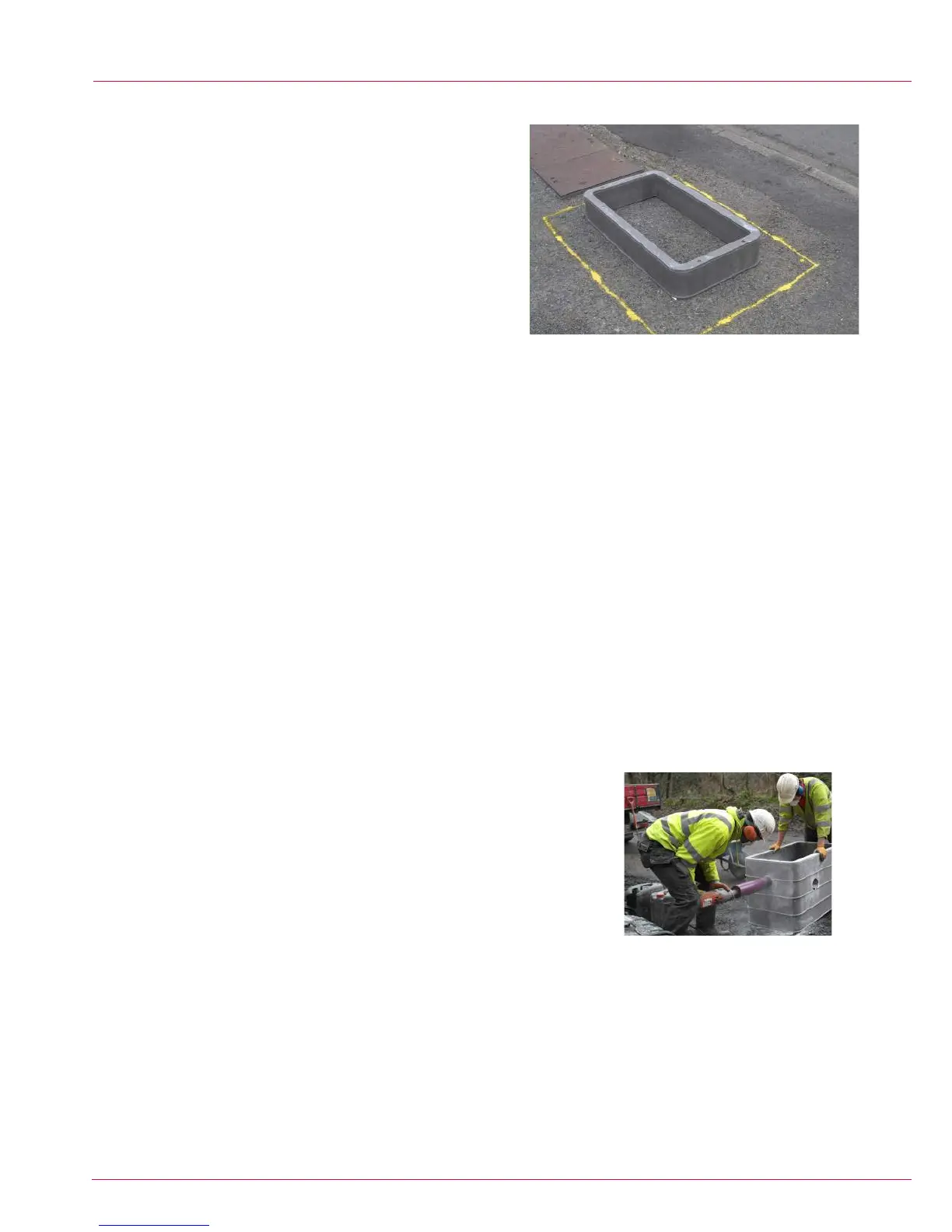
Area of Excavation
1. Mark the extremity of the excavation on the ground. Placing the bottom
section of the chamber on the ground mark around it, allowing either
the minimum thickness of backll as stated in Table 1, or the width of the
compaction plant, whichever is the greater.
The Hole
2. Excavate the hole to the correct depth. The depth of the hole should
measure from nished ground level minus the thickness of the frame &
bedding mortar according to the level specied by the frame and cover
installation, chamber depth and the required base depth (see Table 1 for
base depths).
The Base
3. Compact the bottom of the excavation using a suitable compaction device, making sure that it is level. If there are any “soft areas” these
should be excavated and lled with MOT1 stone or other approved materials, compacted as per the requirements of “Specication for the
Reinstatement of Openings in Highways - Appendix A8” or equivalent national standard.
4. Construct the base using the necessary materials.
4.1. If a drain is required in the chamber it should now be installed as per the client’s specication.
4.2. For compacted stone, level the stone with the shovel and compact as per the requirements of “Specication for the
Reinstatement of Openings in Highways - Appendix A8”.
4.3. For a concrete base, level the C40 concrete and compact as per the requirements of “Specication for the Reinstatement
of Openings in Highways - Appendix A8”. For bases that require reinforcing mesh the base should be constructed in 2 levels, with the
mesh being placed in the middle.
5. The bottom ring section is now carefully positioned on the base. If the chamber system does not have a preformed base,
then the ring should be gently tapped so that it beds down into the base by approximately 10mm. The correct orientation of the chamber
ring is with the horizontal lip to the bottom. Check that the ring is level and at the correct depth. If a concrete base is being used, the
concrete can be oated to give a smoother nish.
The Chamber Walls
6. The additional wall sections are then installed. Make sure that each section is properly inserted to ensure there are no gaps between
Duct Entries
7. Chambers can either have the duct entries factory drilled or can be formed on site.
7.1. For factory drilled chambers remove the duct caps as required.
7.2. Site formed duct entries are best created using a hole-saw and drill, if these tools are
not available then the opening can be formed by using a hand saw or disc cutter to form
a square hole. When the duct is tted the gap between the cut and the duct should be
lled using mortar.
7.3. If using pre-formed bell mouths or chamber entry connectors these can be tted now.
7.4. Insert the ducts into the holes.
7.5. Duct entries should not be formed in the bottom section or the top two sections
without prior approval of CUBIS Industries.
7.6. Duct entries should not be cut within 50mm from the corner.
7.7. The distance between duct entries should be a minimum of half the duct diameter from edge to edge.
7.8. The accumulative diameter of all of the ducts should not constitute more than 20% of the total circumference of the access
chamber section.
7.8.1. In the event of duct entries constituting more than 20% of the total circumference of a section, a structural C40 surround
should be installed up to the uppermost duct entry section ring.
 Loading...