6
INSTALLATION PROCEDURE
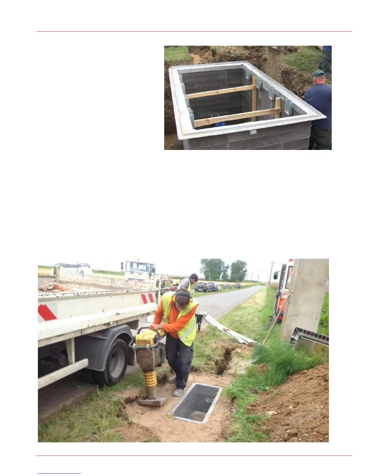
Bracing
10. On certain chambers cross bracing is required. See
Table 1 for details.
10.1. If timber bracing is required this should be
supplied with the chamber. Make sure that the bracing
is vertical and plumb and located in the correct position.
10.2. On larger chambers “Acrow” props are used as
bracing.
These are not supplied by CUBIS. Timber footplates
should be used to disperse the loads evenly over the
chamber. See Table 1 for spacing details.
Backlling
11. With the chamber installed to its nished depth, duct entries formed, furniture tted and if required suitable bracing installed, the backll
surround of the chamber can now take place. Backlling is formed in layers and should be completed to the top of the chamber, or in the
case of a roadway construction to the underside of the blacktop construction. Refer to Table 1 for the recommended backll material and
required width of material.
Refer to “Specication for the Reinstatement of Openings in Highways - Appendix A8” for the depth of layers and number of
passes required for the selected material and compaction method.
11.1. If timber bracing is being used, this should be raised along with the backlling to ensure that there is adequate support for the chamber
wall section that is being compacted against.
11.2. If Acrow props are required these can be left in position until the backll and compaction are completed and the material has adequately
cured.
 Loading...