8 PNEG-2223 Flex-Flo Control Unit with Auto Calibration
2. Operation and Maintenance
Standard Systems
The Flex-Flo Control Unit is primarily controlled by an auxiliary switch, such as a proximity switch or
infrared sensor or hopper level control. Refer to wiring diagrams on Pages 14-24 that matches the auxiliary
switch used. The auxiliary switch is installed underneath the Flex-Flo Control Unit. The Flex-Flo auger can
only run when the auxiliary switch is calling for feed. If the auxiliary switch fails to shut the Flex-Flo auger
OFF when the feed is full, the feed will build-up inside the box behind the control unit and the safety backup
switch will be activated. As a result, the Flex-Flo auger will shut off until the feed drops away.
Extension Systems
The Flex-Flo Control Unit may also be used to control a fill system auger that feeds into an extension
system auger. In the case of an extension system, there is no auxiliary switch used to control the fill system
auger. If the fill system auger is to be controlled independent of the extension system auger, there must
be a jumper wire across the “Auxiliary” switch terminals marked “Signal IN” and “Signal Out” of the fill
system control unit. Refer to wiring diagram for “Flex-Flo Control Unit Extension System - Independent”
on Page 18. When wired this way, the fill system auger is controlled by the safety backup switch.
If the fill system auger is to be controlled by the extension system auger, there needs to be a two (2)
conductor cord from the fill system control unit “Auxiliary” terminals marked “Signal IN” and “Signal Out”,
to the extension system control unit terminals marked “Relay Output”. Refer to wiring diagram for
“Flex-Flo Control Unit Extension System - Dependent” on Pages 15-17. When wired this way, the fill
system auger is controlled by the extension system control unit.
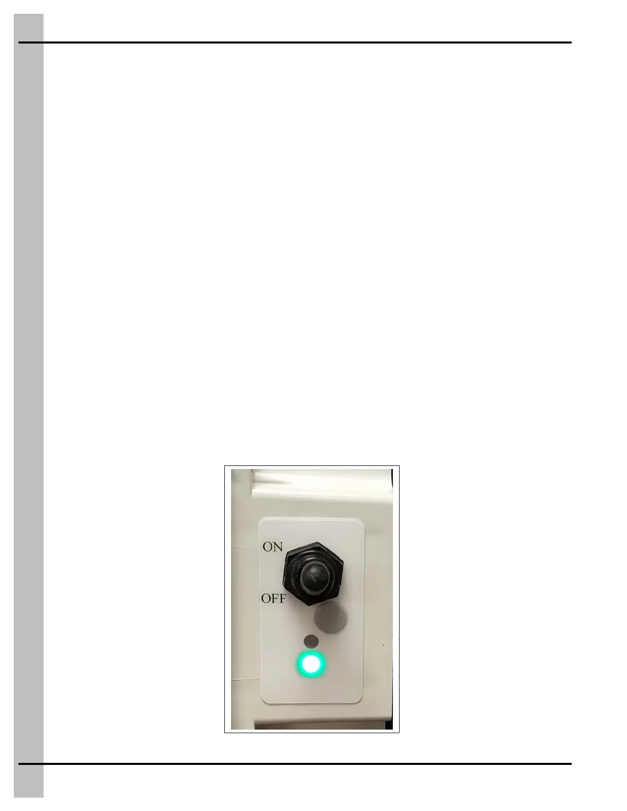
Indicator Lights Under Toggle Switch
Located on the side of the Flex-Flo Control Unit, underneath the toggle switch are multi-color indicator
lights and a grey Manual ON button.
When the bottom light is green, it indicates that the toggle switch is ON and the safety backup switch has
not been activated. In this state, the Flex-Flo auger will run if the auxiliary switch is calling for feed.
(See Figure 2A.)
Figure 2A Control on Box - Green
 Loading...