8 9
NO ELECTRIC TERMINAL DESCRIPTION
CN1 MOTOR OUT MOTOR OUTPUT
CN2 ENCODER MOTOR ENCODER OUT
CN3 POWER 25V AC SUPPLY
CN4 FUSE FUSE - 10A
PHOTOCELL COM : COMMON
TRANSMITTER DATA: TRANSMITTER DATA
PHOTOCELL COM : COMMON
RECEIVER DATA: RECEIVER DATA
CN5 RADAR 1 INTERNAL RADAR
PLUS +12V DC
MINUS -12V DC
COM : COMMON
INP: INPUT
CN6 RADAR 2 EXTERNAL RADAR
PLUS +12V DC
MINUS -12V DC
COM : COMMON
INP: INPUT
CN7 POSITION 1: POSITION 1
(POSITION SWITCH)
2: POSITION 2
COM : COMMON
CN8 UART PC CONNECTION
CN9 OPEN-CLOSE COM : COMMON
(OPEN-CLOSE) CLOSE: CLOSE DATA
OPEN: OPEN DATA
CN10 12V DC 12V DC -MAXIMUM 100mA OUTPUT
DP1 SETUP (DIP SWITCH) INSTALLATION SETTINGS
PT1 OPEN SPEED OPENING SPEED
PT2 CLOSE SPEED CLOSING SPEED
SW1 RESET INSTALLATION REMOVAL
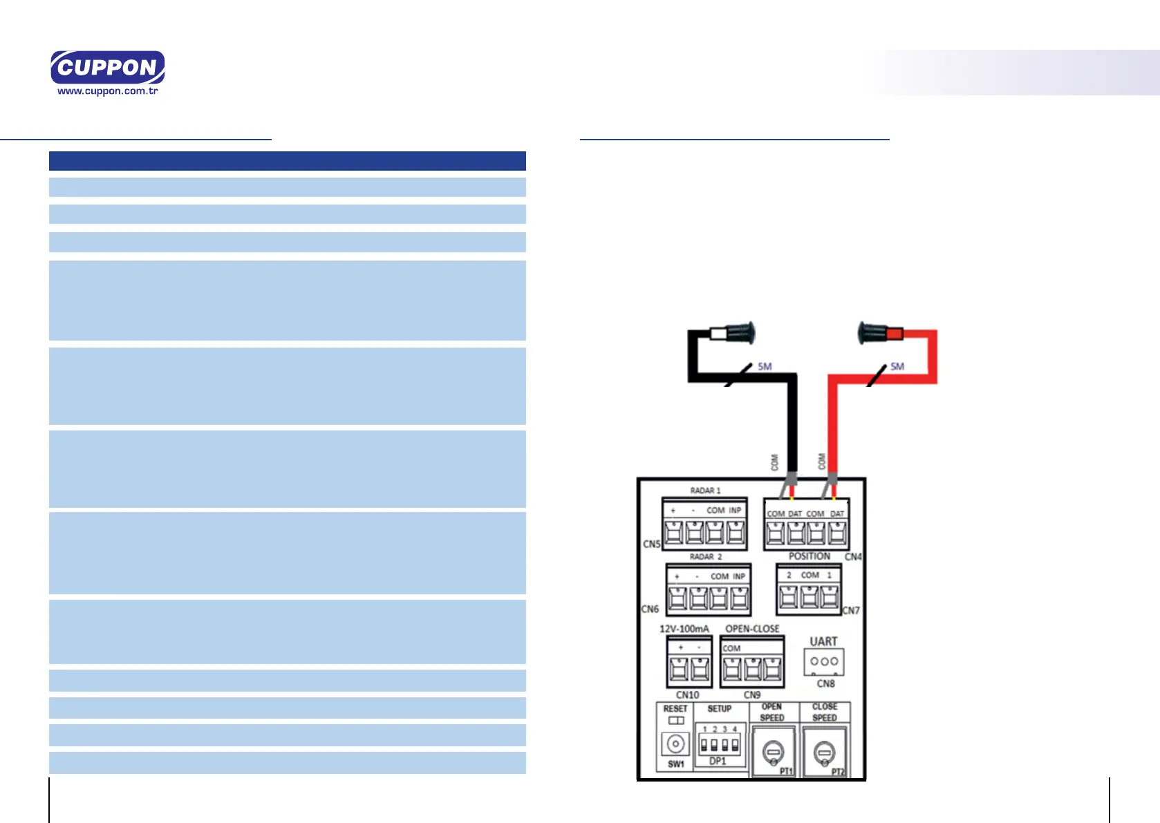
CONNECTIONS
OPERATING FUNCTIONS
Photocell Receiver / Photocell Transmitter
Safety photocell is a system which detects an obstacle found between doors through
infrared signals for safety and control.
In order to ensure an optimum operating efciency, the Receiver and the transmitter
should be level. The highest distance between the photocell transmitter (white) and
photocell receiver (red) should be 5 meters at maximum. Sensors should be vertical, and
on the same line. When transmitter and receiver sensors of the photocell detect each
other, the Photocell Led light on the microprocessor unit illuminates, and when not then
the Photocell Led light turns off. In cases when Photocell Led turns off, please make sure
sensors detect each other by checking the position of sensors.
Photocell Transmitter (TX)
and Photocell Receiver (RX)
cables are 5 meters. In order to
distinguish cables and sensors
of receiver / transmitter, the
Receiver (RX) socket is red,
and Transmitter (TX) socket is
white.
REMARK:
FOR ACTIVATING THE PHOTOCELL,
SET DIP SWITCH 1 TO “ON”.
PHOTOCELL TRANSMITTER
TX (TRANSMITTER)
RX (RECEIVER)
PHOTOCELL RECEIVER
TRANSMITTER RECEIVER
CLOSE-OPEN
CSD 150
AUTOMATIC SLIDING