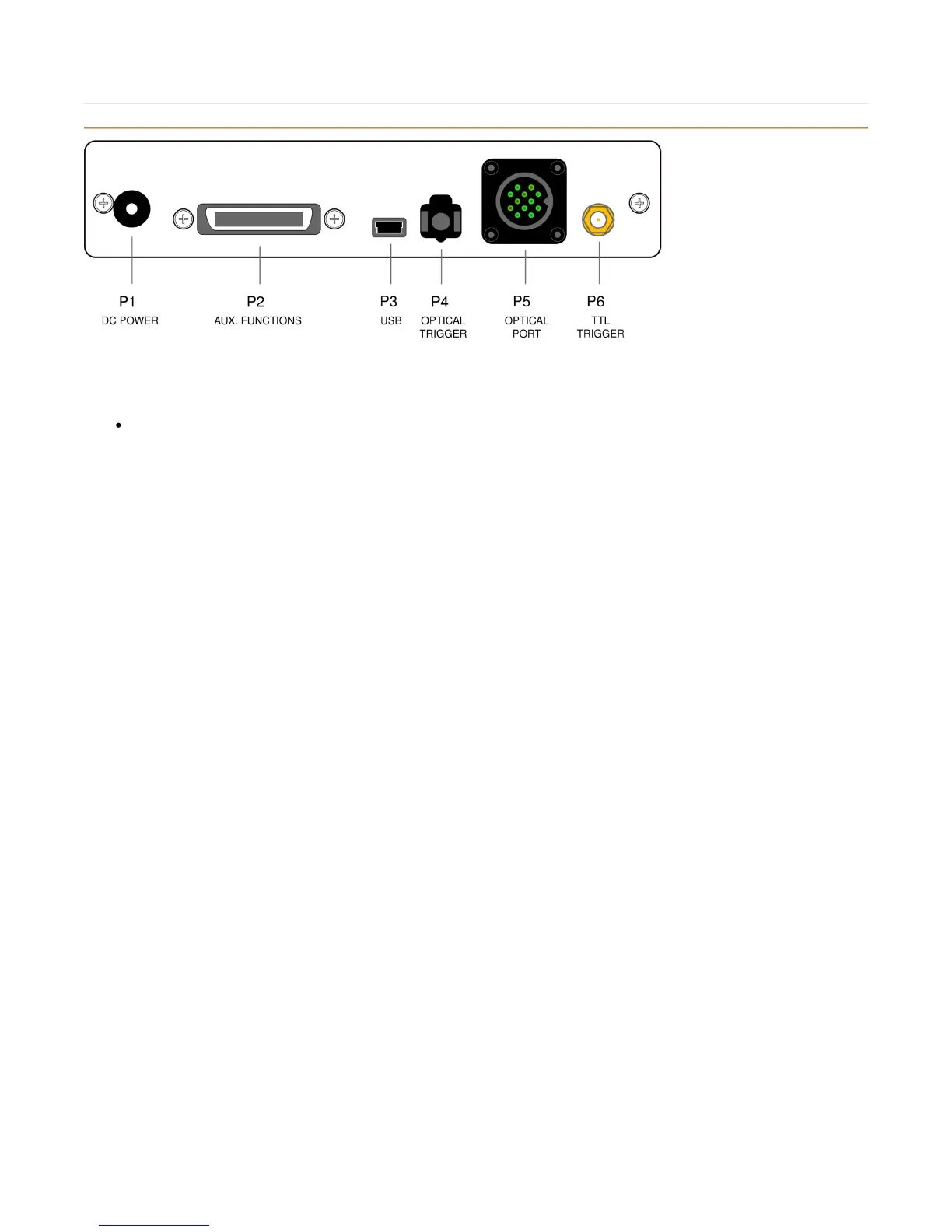
932 Rear Panel
P1: DC Power input
This input should only be used with the power supply provided, which is:
Current Designs Model Number: PS-932-6V
A suitable replacement is: Cui, Inc. Model Number: EPS060175UPS-P5P-KH (6V regulated @ 1.75A max, on a 2.1 mm power
plug).
P2: Aux. functions - S erial and TTL outputs
This port contains the TTL and serial output signals.To use the serial output, use cable Main.CB-932-SER-1. For use with a
parallel port, us cable Main.CB-932-PAR-1.
It is 36 pin MDR type connector. An example mating connector is made by 3M and listed as model number 3M
10136-3000PE.
P3: US B outputs
For most users this is the main data output port.
It is connected to the host computer using a commonly available USB cable (5 pin mini-USB to USB).
P4: Main.Optical trigger input
This port accepts optical trigger signals such as those produced on some Siemens MR scanners. It uses an Agilent HFBR
connector.
P5: Main.Optical Port
This port connects to a Current Designs removable fiber optic bundle or directly to an optical handheld device.
Its has 12 optical pins: 4 transmitting and 8 receiving.
P6: TTL Trigger input
This connector accepts TTL trigger signals.
Triggers are detected on low-to-high (positive-going) edges; there is no minimum pulse width.
Use with cable CB-SMB-BNC-1.
This is an SMB type connector.