10 11
3. INSTALLATION
The Model 908 fits into a dash-panel cutout
measuring 2 ¹/16” (52mm).
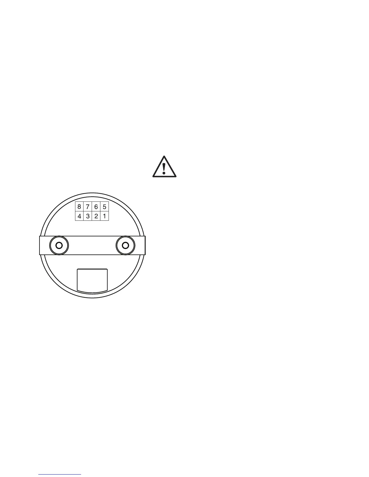
Terminal Assignment (see diagram on page 14)
Pin 7 or 8 = Battery +
Single voltage models: Pin 7 to battery +; Pin 8, open.
Dual voltage models: When vehicle voltage is the
higher voltage of the 2 operating voltages, Pin 8 con-
nects to battery +; Pin 7, open. When vehicle voltage is
the lower of the 2 operating voltages, Pin 7 connects to
battery +, Pin 8, open.
The discharge indicator uses Pin 7 or 8 for its battery
state-of-charge measurements. Connection are to be
made as close as possible to battery to prevent voltage
drops that will cause errors in discharge indicator
readings. The connection is not to be switched by the
vehicle’s keyswitch.
Pin 5 = Battery –
Connect to battery ground as close to battery
as possible.
CURTIS Model 908 Rear View