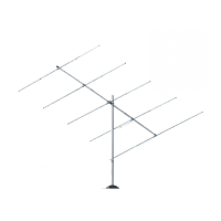
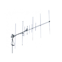
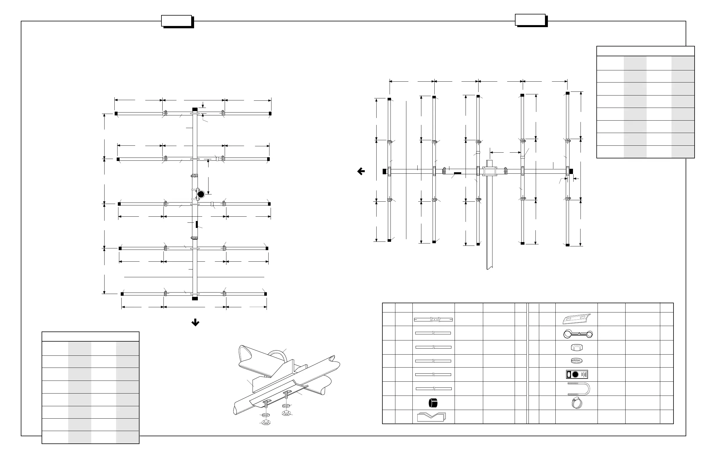
#2 - ELEMENT ASSEMBLY & MOUNTING
The elements are made up of one pre-drilled and slotted 3/4" (1.9 cm) O.D. center tube and two pre-cut 5/8" (1.59 cm) O.D. end tubes. Assemble
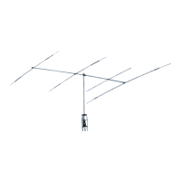
the elements using Figure B for horizontal polarization or Figure B-2 for vertical polarization. Slide the tuning strap (69) on one of the EA tubes.
This will be the driven element #2. Place telescope clamps (409) loosely on the slotted ends of all EA tubes. Note that the EC tubes must be used
with the EA tube on which you placed the tuning strap (69). Attach caps (27) to the end of each element. Mount the elements to the boom (Figure
C). Refer to figure D for mounting the dipole element with the connector bracket. Mount the connector with the threads (socket) pointing to the
mast mount. Adjust the antenna to your preferred portion of the 6 meter band using Table 1 if you've chosen horizontal polarization or Table 2 for
vertical polarization. Tighten all connections.
Horizontal Polarization
50 MHz- 51.5 MHz- 53 MHz
51.5 MHz 53 MHz 54 MHz
REF in. 35-1/8 34 32-1/8
(cm) (89.22) (86.36) (81.60)
DE in. 31-3/4 28-3/8 26-7/8
(cm) (80.64) (72.07) (68.26)
D1 in. 29-3/4 27 26-1/4
(cm) (75.56) (68.58) (66.67)
D2 in. 29-3/4 24-7/8 24-5/8
(cm) (75.56) (63.18) (62.55)
D3 in. 25-5/8 24-1/2 23-1/2
(cm) (65.09) (62.23) (59.69)
Set in. 15-5/8 16-1/2 17
(cm) (39.69) (41.91) (43.18)
X in. 1-7/8 3 3
(cm) (4.76) (7.62) (7.62)
FIGURE C
Vertical Polarization
50 MHz- 51.5 MHz- 53 MHz
51.5 MHz 53 MHz 54 MHz
REF in. 37-1/2 35-1/2 33-1/2
(cm) (95.25) (90.17) (85.09)
DE in. 30-3/4 30-3/4 30-3/4
(cm) (78.10) (78.10) (78.10)
D1 in. 30 28 26
(cm) (76.2) (71.12) (66.04)
D2 in. 29-1/2 27-1/2 25-1/2
(cm) (74.93) (69.85) (64.77)
D3 in. 29 27 25
(cm) (73.66) (68.58) (63.5)
Set in. 15-5/8 15-5/8 18
(cm) (39.69) (39.69) (45.72)
X in. 2 2 1-1/2
(cm) (5.08) (5.08) (3.81)
EA ALUM 3/4" x 48" 5
TUBING (1.9 x 121.9 cm)
EB ALUM 5/8" x 40-1/2" 2
TUBING (1.6 x 102.9 cm)
EC ALUM 5/8" x 35-3/4" 2
TUBING (1.6 x 90.8 cm )
ED ALUM 5/8" x 33" 2
TUBING (1.6 x 83.8 cm )
EE ALUM 5/8" x 32-1/2" 2
TUBING (1.6 x 82.5 cm)
EF ALUM 5/8" x 32" 2
TUBING (1.6 x 81.3 cm )
27 050027 PLASTIC 5/8" 10
CAP (1.59 cm)
32 190032 U-BOLT 1-1/2" 5
BRACKET (3.8 cm)
KEY P/N DISPLAY DESC SIZE QTYKEY P/N DISPLAY DESC SIZE QTY
33 190033 BACKING 1-1/2" 4
PLATE (3.8 cm)
69 200069 TUNING 1
STRAP
85 010085 HEX 1/4" 10
NUT (.63 cm)
84 010084 LOCK 1/4" 10
WASHER (.63 cm)
326 290326 DANGER 1
LABEL
402 010402 U-BOLT 1-1/2" 5
(3.8 cm)
409 030409 WORM 3/4" 10
CLAMP (1.9 cm)
Table 2
FIGURE B
Horizontal
Polarization
FIGURE B-2
(Vertical Polarization)
Table 1
EE
EE
EA
48"
(121.9 cm)
31.0"
(78.7 cm)
EC EC
48"
(121.9 cm)
DE
FRONT
EA
69
27
27
409
409
ED
ED
35"
(88.9 cm)
27
27
27
27
409
69
409
409
EA
#1 - REFLECTOR
#2 - DRIVEN
ELEMENT
#4 - DIRECTOR
BB
AA
D1
D1
DE
48"
(121.9 cm)
D2
D2
326
EB EB
48"
(121.9 cm)
REF
2"
(5.1 cm)
27
27
409
409
EA
BB
REF
EF
EF
EA
27
27409
409
#5 - DIRECTOR
48"
(121.9 cm)
D3
D3
35"
(88.9 cm)
35"
(88.9 cm)
35"
(88.9 cm)
#3 - DIRECTOR
409
EE
EE
EA
48"
(121.9 cm)
31"
(78.7 cm)
EC
EC
48"
(121.9 cm)
DE
FRONT
EA
69
27
27
409
409
ED
ED
35"
(88.9 cm)
27
27
27
27
409
409
409
409
69
#1 - REFLECTOR#2 - DRIVEN ELEMENT#4 - DIRECTOR
BB
AA
D1
D1
DE
48"
(121.9 cm)
D2
D2
EB
EB
48"
(121.9 cm)
REF
2"
(5.1 cm)
27
27
409
409
EA
BB
REF
EF
EF
EA
27
27
409
409
#5 - DIRECTOR
48"
(121.9 cm)
D3
D3
35"
(88.9 cm)
35"
(88.9 cm)
35"
(88.9 cm)
#3 - DIRECTOR
EA
326
402
32
33
84
85
84
85
3
4
A50-5S
A50-5S
 Loading...