EasyManua.ls Logo

Custom Dynamics MAGIC-STROBES-SS6 - User Manual

Custom Dynamics MAGIC-STROBES-SS6
2 pages
Print Icon
To Next Page IconTo Next Page
Loading...
Custom Dynamics® Magic Strobes™ Brake Flasher
Installation Instructions
We thank you for purchasing the Custom Dynamics® Magic Strobes
Brake Light Flasher! Our products utilize the latest technology and
high quality components to ensure you the most reliable service. We
offer one of the best warranty programs in the industry and we back
our products with excellent customer support, if you have questions
before or during installation of this product please call Custom
Dynamics® at 1(800) 382-1388.
Questions? Call us at: 1 (800) 382-1388 M-TH 8:30AM-5:30PM / FR 9:30AM-5:30PM EST
08-2015SM
Part Number: MAGIC-STROBES-SS6
Installation
Package Contents:
- Magic Strobes™ Brake Flasher (1)
- Tie Wraps (5)
Fits: 2010-13 Street Glide, 2010-2013 Road Glide Custom
ATTENTION
Please read all Information below before Installation
Important: Module must be secured after installa-
tion. Find safe area away from any moving parts and
out of the way of normal operation of the bike. Use the
enclosed tie-wraps to secure. Custom Dynamics® is
not liable for damage as a result of improperly securing
or failing to secure the
module.
Note: When using a Magic Strobe™ with a Signal
Stabilizer™ or other Load Equalizer we recommend to
install the Magic Brake Strobe™ after (towards the
taillight) the Signal Stabilizer or Load Equalizer. (See
Diagram)
Important: Customers using this module with
standard incandescent bulbs should use patterns 0-3
only. Any other settings selected will result in dimin-
ished performance.
Caution: A stuck brake switch may cause this unit
to overheat and fail . Unplug module immediately if this
condition occurs.
Note: Although this device has been designed to significantly in-
crease your braking visibility, flash/strobe patterns may not be street
legal in your area. This Device is not DOT approved.
1. Secure motorcycle on level surface.
2. Remove kickstand side panel to access wiring.
3. Disconnect negative [ - ] battery cable from
the battery.
4. Locate and unplug the lighting connector to the
rear fender.
5. Plug the Magic Strobes™ Module, in-line, into
the rear lighting harness and into the bike’s
wiring harness.
6. Re-connect the battery’s negative battery
cable to the negative [ - ] of the battery.
7. Select Desired Pattern on the dial with power
Off. (See page 2 for Pattern Information)
8. Check Operation.
9. To change pattern, turn bike OFF and change
dial to desired pattern.
10. Locate a secure place for the Magic Strobes™
unit that will not interfere with the secure
placement of the seat. Secure with the en-
closed tie-wraps so that unit will not move.
Question and Answer IconNeed help?

Do you have a question about the Custom Dynamics MAGIC-STROBES-SS6 and is the answer not in the manual?

Summary

Custom Dynamics Magic Strobes Brake Flasher Installation Instructions

Package Contents Overview

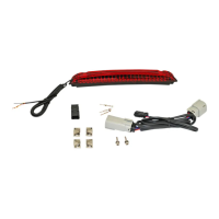
Lists the components included in the Magic Strobes Brake Flasher kit.

Installation Steps Guide

Step-by-step instructions for installing the brake flasher module on the motorcycle.

Important Safety and Usage Warnings

Critical information regarding module security, bulb compatibility, and potential issues.

Flash Pattern and Module Placement Details

Flash Pattern Descriptions

Detailed explanations of the various flash patterns available for the brake flasher.

Module Placement Recommendations

Guidance on correct and incorrect placement of the Magic Strobes module.

Overview

The Custom Dynamics® Magic Strobes™ Brake Flasher is a device designed to enhance braking visibility for motorcycles by adding various flash and strobe patterns to the brake light. It is intended to be an aftermarket accessory that integrates with the motorcycle's existing wiring harness.

Function Description:

The primary function of the Magic Strobes™ Brake Flasher is to modify the standard brake light operation to include a series of flashes or strobes before the light remains solid. This flashing action is designed to draw more attention to the motorcycle when the brakes are applied, potentially increasing safety by making the braking action more noticeable to other drivers. The device offers a range of selectable patterns, allowing the user to choose the desired flashing sequence. It operates by being installed in-line with the rear lighting harness, effectively intercepting and modifying the signal sent to the brake light. The module is compatible with both incandescent and LED brake lights, although certain patterns are optimized specifically for LED lights.

Usage Features:

Installation:

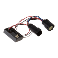
The installation process involves securing the motorcycle on a level surface, removing the kickstand side panel to access wiring, and disconnecting the negative battery cable for safety. The user then locates and unplugs the lighting connector to the rear fender. The Magic Strobes™ Module is then plugged in-line between the rear lighting harness and the bike's wiring harness. After installation, the negative battery cable is reconnected.

Pattern Selection:

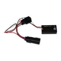
The device features a dial for selecting different flash patterns. To change a pattern, the motorcycle must be turned OFF. The user then rotates the dial to the desired pattern number. The manual provides a detailed "Flash Pattern Information" section, illustrating each pattern and indicating whether it is suitable for incandescent or LED lights, or LED only.

  • Pattern 0: Four Flashes then Solid (Incandescent or LED) - The brake light flashes four times and then remains solid.
  • Pattern 1: Four Flashes, Solid for 3 Seconds, Repeat (Incandescent or LED) - The brake light flashes four times, stays solid for three seconds, and then repeats the sequence.
  • Pattern 2: Seven Flashes then Solid (Incandescent or LED) - The brake light flashes seven times and then remains solid.
  • Pattern 3: Seven Flashes, Solid for 3 Seconds, Repeat (Incandescent or LED) - The brake light flashes seven times, stays solid for three seconds, and then repeats the sequence.
  • Pattern 4: Quad Strobe then Solid for 1 Second then Quad Strobe (LED Only) - The brake light performs a quad strobe, stays solid for one second, and then performs another quad strobe.
  • Pattern 5: Quad Strobe, Solid for 1 Second, then Quad Strobe, Solid for 3 Seconds, then Repeat (LED Only) - The brake light performs a quad strobe, stays solid for one second, then performs another quad strobe, stays solid for three seconds, and then repeats the sequence.
  • Pattern 6: Blaster X Pattern for 3 seconds, then Solid (LED Only) - The brake light performs a Blaster X pattern for three seconds and then remains solid.
  • Pattern 7: Constant Blaster X Pattern (LED Only) - The brake light continuously performs a Blaster X pattern.
  • Pattern 8: Constant Fast Strobe 5 Seconds, then Solid (LED Only) - The brake light performs a constant fast strobe for five seconds and then remains solid.
  • Pattern 9: Constant Fast Strobe Pattern (LED Only) - The brake light continuously performs a constant fast strobe pattern.

Compatibility with Load Equalizers/Signal Stabilizers:

The manual specifies that when using the Magic Strobes™ with a Signal Stabilizer™ or other Load Equalizer, the Magic Brake Strobe™ should be installed after (towards the taillight) the Signal Stabilizer or Load Equalizer. A diagram is provided to illustrate the correct placement.

Bulb Type Considerations:

For customers using standard incandescent bulbs, it is important to note that only patterns 0-3 should be used. Selecting any other settings with incandescent bulbs will result in diminished performance. Patterns 4-9 are specifically designed for LED lights.

Secure Placement:

After installation, the module must be secured in a safe area, away from any moving parts and out of the way of normal operation of the bike. The enclosed tie-wraps should be used to ensure the unit does not move. Improperly securing or failing to secure the module can lead to damage, for which Custom Dynamics® is not liable.

Brake Switch Caution:

A critical caution is provided regarding a stuck brake switch. A stuck brake switch may cause the unit to overheat and fail. If this condition occurs, the module should be unplugged immediately.

The manual includes a note stating that while the device is designed to significantly increase braking visibility, the flash/strobe patterns may not be street legal in all areas. The device is explicitly stated as not being DOT approved.

Maintenance Features:

The manual does not explicitly detail specific maintenance features for the Magic Strobes™ Brake Flasher itself. However, the design implies a "set it and forget it" approach once installed and the desired pattern is selected. The primary "maintenance" aspect for the user would involve ensuring the module remains securely fastened and monitoring for any signs of malfunction, such as overheating, as indicated by the caution regarding a stuck brake switch. The robust design and high-quality components mentioned in the introduction suggest a product built for reliability, minimizing the need for frequent user intervention or maintenance. The warranty program also implies a focus on product longevity and support for any manufacturing defects.

Custom Dynamics MAGIC-STROBES-SS6 Specifications

General IconGeneral
Product NameMAGIC-STROBES-SS6
CategoryMotorcycle Accessories
CompatibilityUniversal
Input Voltage12VDC
Waterproof RatingIP67
Voltage12V

Related product manuals