Custom Dynamics® Magic Strobes™ Brake Flasher
Installation Instructions
We thank you for purchasing the Custom Dynamics® Magic Strobes™
Brake Light Flasher! Our products utilize the latest technology and
high quality components to ensure you the most reliable service. We
offer one of the best warranty programs in the industry and we back
our products with excellent customer support, if you have questions
before or during installation of this product please call Custom
Dynamics® at 1(800) 382-1388.
Questions? Call us at: 1 (800) 382-1388 M-TH 8:30AM-5:30PM / FR 9:30AM-5:30PM EST
10-2017
Part Number: MAGIC-STROBES-HD
Installation
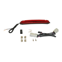
Package Contents:
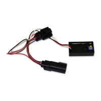
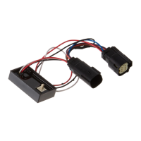
- Magic Strobes™ Brake Flasher (1)
- Tie Wraps (5)
Fits: 1996-2010 Harley-Davidson® Softail® (Except
Convertible, Rocker and Breakout®), 1997-2011
Dyna®, 1997-2013 Touring (Except 2010-2013 Street
Glide®, Road Glide® Custom), 1999-2003 Sportster®,
2010-2013 TriGlide®, and 2011-2013 Road Glide®
Ultra
ATTENTION
Please read all Information below before Installation
Note: When installing the Magic Strobe™ on a 2010-2013
TriGlde®, the Magic-Strobes™ must be installed before the
stock brake-turn module.
Important: Module must be secured after installation. Find
safe area away from any moving parts and out of the way of
normal operation of the bike. Use the enclosed tie-wraps to
secure. Custom Dynamics® is not liable for damage as a
result of improperly securing or failing to secure the module.
Note: When using a Magic Strobes™ with a Smart Signal
Stabilizer™ or other load equalizer we recommend to install
the Magic Strobes™ after (towards the taillight) the Smart
Signal Stabilizer™ or load equalizer. (See Diagram)
Note: When using a Magic Brake Strobes™ with a Non Cus-
tom Dynamics® Run-Brake-Turn Controller, we recommend
the following:
-To flash Brake and turns, Install Magic Strobes™ Before Run
-Brake-Turn Controller. (See Diagram)
-To flash only the center taillight, install Magic Strobes™ After
Run-Brake-Turn Controller. (See Diagram)
Note: Do not Install any Custom Dynamics Magic Strobes™
unit with Custom Dynamics® Smart Triple Play® unit.
Important: Customers using this module with standard incan-
descent bulbs should use patterns 0-3 and 9 only. Any other
settings selected will result in diminished performance.
Caution: A stuck brake switch may cause this unit to over-
heat and fail. Unplug module immediately if this condition
occurs.
Note: Although this device has been designed to significantly in-
crease your braking visibility, flash/strobe patterns may not be street
legal in your area. This device is not DOT approved.
1. Secure motorcycle on level surface.
2. Remove seat or side panel, depending on model.
3. Disconnect negative [ - ] battery cable from the
battery.
4. Locate and unplug the lighting connector to the rear
fender.
5. Plug the Magic Strobes™ module, in-line, into the
rear lighting harness and into the bike’s wiring har-
ness.
6. Re-connect the battery’s negative battery
cable to the negative [ - ] of the battery.
7. Select desired pattern on the dial with power Off.
(See page 2 for Pattern Information)
8. Check operation.
9. To change pattern, turn bike OFF and change dial
to desired pattern.
10. Locate a secure place for the Magic Strobes™ unit
that will not interfere with the secure placement of
the seat. Secure with the enclosed tie-wraps so that
unit will not move.