Quick Start Guide
Battery Management System
BM100
BP100-12V
Battery Management System
BM100
BP100-12V
Copyright © 2017 Cyber Power Systems, Inc. All rights reserved.
1
32
INSTALLATION GUIDE
PRODUCT CONTENTS
Power Cable*
(244cm; L4)
Communication Cable (x4)
(90cm; L1)
2 Mounting Brackets
4 Bracket Mounting Screws
DB9/RJ45 Communication Cable
(183cm)
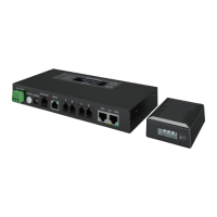
Battery Manager
BM100
Battery Manager Battery Probe
Battery Probe
BP100-12V
Battery Connecting Cable
(30cm; L3)
Probe Communication Cable
(30cm; L2)
1. Connect the battery connecting cable (L3) to each battery and then
connect the cable to each Battery Probe through battery connector
(CN3).
2. Fix each Battery Probe to each battery with Loop tape.
3. Connect the Battery Manager’s ‘A’ (RJ25) port to the ‘Left’ (‘In’)
RJ25 port (CN1) of the first Battery Probe with the communication
cable (L1).
4. Connect Battery Probes with one another through RJ25 ports (CN1)
of Battery Probes with probe communication cables (L2), and up to
40 Battery Probes in a string.
5. Connect an Ethernet cable to the Ethernet port of the Manager.
6. Provide power to the Battery Manager through the DC power (CN4).
The required Battery Manager input voltage is 15V min, 60V max.
Scenario
①
For 4 or less batteries per string: Use the included power cable (L4)
to connect the Battery Manager. (Warning: A battery can present a
high risk of short circuit current and electrical shock. Please pay
attention to the input voltage.)
Scenario
②
For 5 or more batteries per string: Connect the Battery Manager to
the utility power with an AC/DC adapter cord.
7. Press the RESTART button for one second to restart the system.
8. IP address will show on the LCD interface once the Manager is
powered and the system is initialized, or you can find it through
[About → Network info. → IPv4 address]. Use the IP address to
login to the Web Interface. The factory default Username/Password
is admin/admin.
NOTE: Once the number of battery string and connected battery has been
changed from last configuration, please configure it via web interface on
the [Battery → Configuration], select the number of string(s) and
batteries per string, and then click Apply. Or you can reset the system to
the factory default setting via LCD interface on the [Reset/Reboot →
Reset → Confirm].
Baery #1
L3
Probe
CN3
CN1
Baery #2
L3
Probe
CN3
CN1
Baery #3
L3
Probe
CN3
CN1
D
C
B
A
CN4
Battery
Manager
L4 (Scenario ①)
L1
Ethernet
L2
L2
Max. 40 batteries
*For 4 or less batteries per string.
Baery #4
L3
Probe
CN3
CN1
AC/DC
Adapter (Scenario ②)
L2