DDCCTI
VIDEO
DC 5V
EQUALIZER1 2
GAIN
ADJUST
CTI
250M
150M
100M
50M
MIN
MAX
CAT5 INPUT
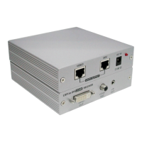
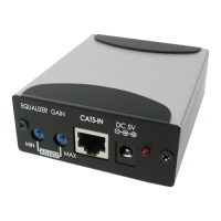
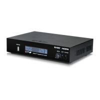
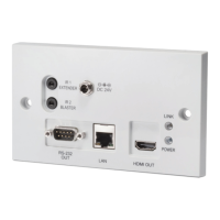
6.2 Receiver’s Front Panel
①
CTI dip switch – Setting CTI by using the twin jumpers to adjust the
optimized setting for different distance of connection.
②
EQUALIZER – Use this switch to adjust Sharpness/Peak over long distance
by turning right or left.
③
GAIN – Use this switch to adjust Brightness/Contrast by turning right or left.
④
DDC CAT 5 INPUT – Connect the DDC input to the DDC output of the
transmitter with CAT-5/CAT-5E/CAT-6 cable.
Note:
For advanced user only, if it's known that the DDC or HDCP data
are required for the source and the display, you can use a single CAT-5
cable for the VIDEO connection only.
⑤
VIDEO CAT 5 INPUT – Connect the VIDEO input to the Video output of the
transmitter with CAT-5/CAT-5E/CAT-6 cable.
⑥
Power Jack – Connect with 5V / 2.6A power adaptor with power supply.
CTI 1 2
150
-
250m
↑ ↑
100
-
150m
↓ ↑
50
-
100m
↑ ↓
50
m
↓ ↓ ↓
1 2 3 4 5 6