Do you have a question about the Cyrus 8 Qx DAC and is the answer not in the manual?
Guidelines for handling components to prevent static damage during servicing.
Requirements for using lead-free components and solder in repairs.
Emphasis on using original components for preserving sound quality.
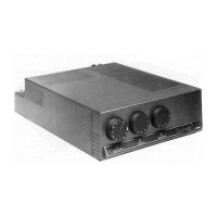
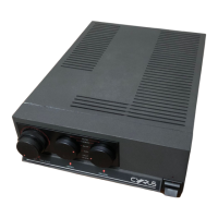
Details on construction and power output differences between models.
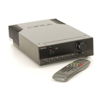
Information on factory-offered upgrades to higher specification models.
Detailed technical parameters for the Cyrus 6 DAC analogue section.
Detailed technical parameters for the Cyrus 8 DAC analogue section.
Digital specifications for Cyrus 6 DAC and 8 DAC models.
Digital specifications specific to the Cyrus 8 Qx DAC model.
Information found on the rating label and model number display.
Importance and details of the amplifier's serial number for service.
Guidance on identifying PCBs using revision and marking numbers.
Precautions for storing and handling SMD resistors, capacitors, and ICs.
Measures to prevent static damage to sensitive electronic components.
Techniques and tools for safely replacing SMD components.
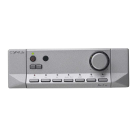
Description of analogue input selection and digital input processing.
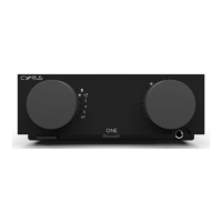
Details on volume control, power amplifier design, and standby.
Description of power supply, headphone amp, and protection mechanisms.
Explanation of the microcontroller-based control system and PCB connections.
Differences between control PCB versions and replacement procedures.
Overview of amplifier construction and steps for safe dismantling.
Safety measures before power-up and initial diagnostic tests.
Steps for diagnosing power amplifier and power supply faults.
Fault finding for preamplifier, control system, and digital audio sections.
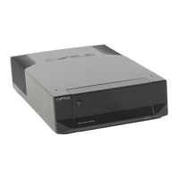
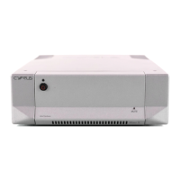
Details of PSX-R power supply connections and operational modes.
Step-by-step guide for setting quiescent current after amplifier repair.
Routine procedure for checking and setting DC offset at speaker terminals.
Procedure for testing the MC-BUS communication loop between Cyrus products.
Information on upgradeable software and procedures for re-programming.
Circuit diagrams for the main PCB, covering various sections.
Circuit diagrams for the sub PCB, detailing its functional blocks.